Line inputs, Table 3. microphone input registers (continued) – Rainbow Electronics MAX98088 User Manual
Page 67
Stereo Audio Codec
with FLEXSOUND Technology
MAX98088
67
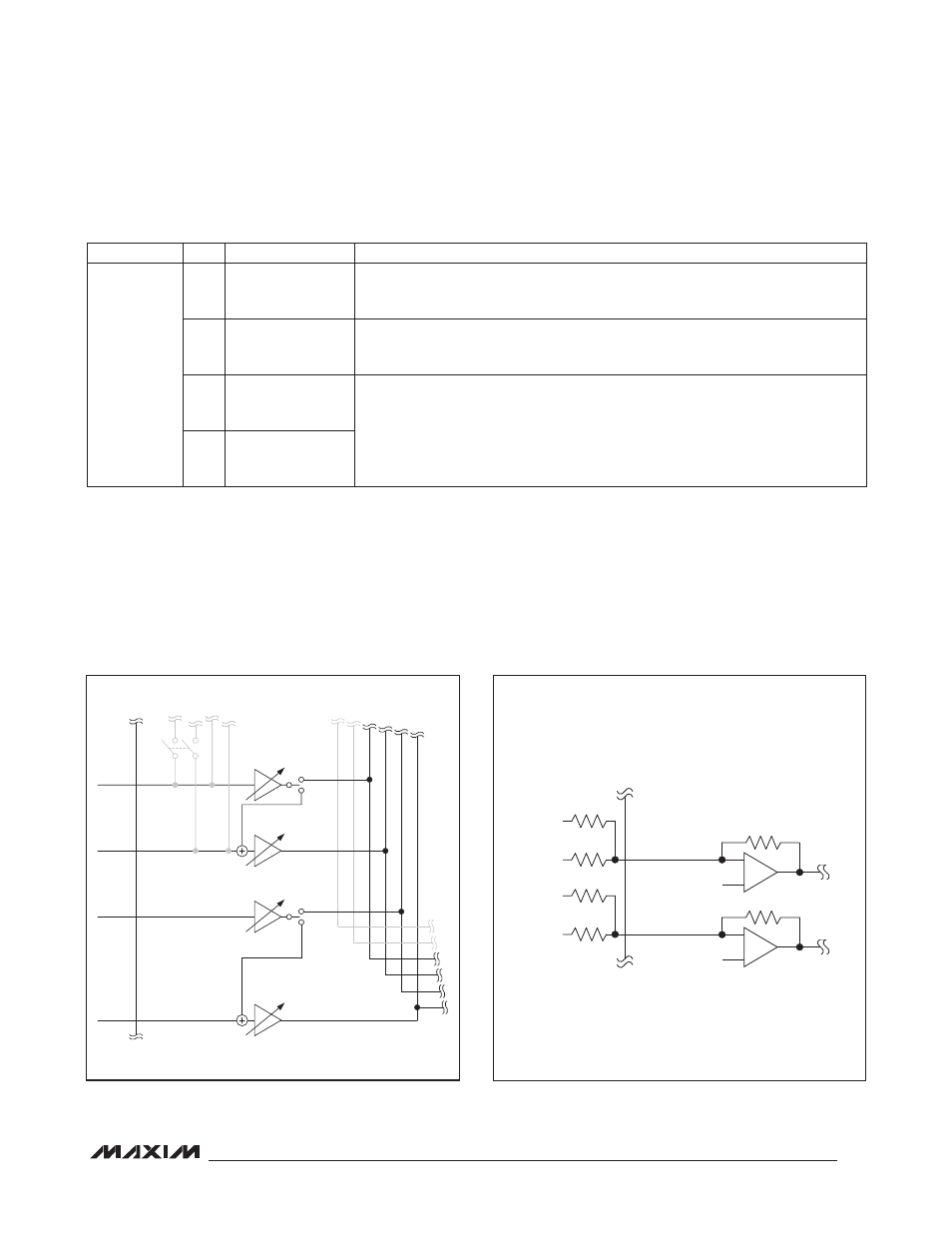
Line Inputs
The device includes two sets of line inputs (Figure 7).
Each set can be configured as a stereo single-ended
input or as a mono differential input. Each input includes
adjustable gain to match a wide range of input signal
levels. If a custom gain is needed, the external gain
mode provides a trimmed feedback resistor. Set the gain
by choosing the appropriate input resistor and using the
following formula:
AV
PGAIN
= 20 x log (20K/RIN)
The external gain mode also allows summing multiple
signals into a single input, by connecting multiple input
resistors as show in Figure 8, and inputting signals larger
than 1V
P-P
.
Table 3. Microphone Input Registers (continued)
Figure 7. Line Input Block Diagram
Figure 8. Summing Multiple Input Signals into INA/INB
REGISTER
BIT
NAME
DESCRIPTION
0x4A
7
INABYP
INA_/EXTMIC_ to MIC1_ Bypass Switch
0 = Disabled
1 = Enabled
4
MIC2BYP
MIC1_ to MIC2_ Bypass Switch
0 = Disabled
1 = Enabled
1
RECBYP
See the Output Bypass Switches section.
0
SPKBYP
INADIFF
PGAINA:
+20dB TO -6dB
INABYP
INBDIFF
INA1/
EXTMICP
INA2/
EXTMICN
INB1
INB2
PGAINA:
+20dB TO -6dB
PGAINB:
+20dB TO -6dB
PGAINB:
+20dB TO -6dB
LEFT
INPUT 1
LEFT
INPUT 2
INA1/EXTMICP
VCM
INA2/EXTMICN
20kI
RIGHT
INPUT 1
RIGHT
INPUT 2
VCM
20kI