Pin description (continued) – Rainbow Electronics MAX98088 User Manual
Page 55
Stereo Audio Codec
with FLEXSOUND Technology
MAX98088
55
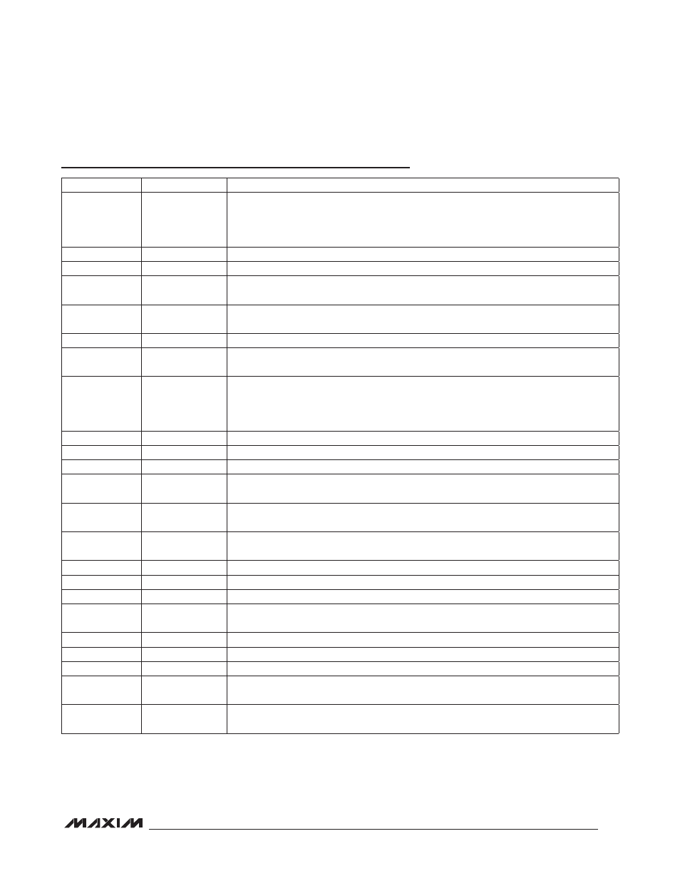
Pin Description (continued)
PIN
NAME
FUNCTION
E5
IRQ
Hardware Interrupt Output. IRQ can be programmed to pull low when bits in status register
0x00 change state. Read status register 0x00 to clear IRQ once set. Repeat faults have
no effect on IRQ until it is cleared by reading the I
2
C status register 0x00. Connect a 10kI
pullup resistor to DVDD for full output swing.
E6
JACKSNS
Jack Sense. Detects the insertion of a jack. See the Jack Detection section.
E7
INB1
Single-Ended Line Input B1. Also negative differential line input B.
E8
MIC1P/
DIGMICDATA
Positive Differential Microphone 1 Input. AC-couple a microphone with a series 1FF
capacitor. Can be retasked as a digital microphone data input.
E9
INA2/
EXTMICN
Single-Ended Line Input A2. Also positive differential line input A or negative differential
external microphone input.
F1
DGND
Digital Ground
F2
BCLKS2
S2 Digital Audio Bit Clock Input/Output. BCLKS2 is an input when the IC is in slave mode
and an output when in master mode. The input/output voltage is referenced to DVDDS2.
F3
LRCLKS2
S2 Digital Audio Left-Right Clock Input/Output. LRCLKS2 is the audio sample rate clock
and determines whether audio data on S2 is routed to the left or right channel. In TDM
mode, LRCLKS2 is a frame sync pulse. LRCLKS2 is an input when the IC is in slave mode
and an output when in master mode. The input/output voltage is referenced to DVDDS2.
F4
SDA
I
2
C Serial-Data Input/Output. Connect a pullup resistor to DVDD for full output swing.
F5
SCL
I
2
C Serial-Clock Input. Connect a pullup resistor to DVDD for full output swing.
F6
REG
Common-Mode Voltage Reference. Bypass to AGND with a 1FF capacitor.
F7
MICBIAS
Low-Noise Bias Voltage. Outputs a 2.2V microphone bias. An external resistor in the 2.2kI
to 1kI range should be used to set the microphone current.
F8
MIC1N/
DIGMICCLK
Negative Differential Microphone 1 Input. AC-couple a microphone with a series 1FF
capacitor. Can be retasked as a digital microphone clock output.
F9
INA1/
EXTMICP
Single-Ended Line Input A1. Also negative differential line input A or positive differential
external microphone input.
G1
SDOUTS2
S2 Digital Audio Serial-Data ADC Output. The output voltage is referenced to DVDDS2.
G2
DVDDS2
S2 Digital Audio Interface Power-Supply Input. Bypass to DGND with a 1FF capacitor.
G3
SDINS2
S2 Digital Audio Serial-Data DAC Input. The input voltage is referenced to DVDDS2.
G4
DVDD
Digital Power Supply. Supply for the digital core and I
2
C interface. Bypass to DGND with a
1FF capacitor.
G5
AVDD
Analog Power Supply. Bypass to AGND with a 1FF capacitor.
G6
REF
Converter Reference. Bypass to AGND with a 2.2FF capacitor.
G7
AGND
Analog Ground
G8
MIC2N
Negative Differential Microphone 2 Input. AC-couple a microphone with a series 1FF
capacitor.
G9
MIC2P
Positive Differential Microphone 2 Input. AC-couple a microphone with a series 1FF
capacitor.