Rainbow Electronics MAX6683 User Manual
Page 9
ALERT
Interrupts
An out-of-range voltage or temperature causes the
ALERT output signal to be asserted. However, if the
assertion is caused by an out-of-range temperature, the
ALERT output can operate in one of three different
modes: default, one-time interrupt, or comparator
mode. In the default and one-time interrupt modes, the
ALERT signal and Interrupt Status Register are cleared
by reading the Interrupt Status Register (Table 5). In
comparator mode, ALERT is only cleared when the fault
condition is removed. Reading the Interrupt Status
Register clears all but bit 4 of the Status Register if the
fault condition is not removed. Reading the Interrupt
Status Register with the fault condition removed clears
the entire register. Unless the fault is removed, ALERT
is reasserted after the next conversion cycle. The
ALERT output can also be masked by writing to the
appropriate bits in the Interrupt Mask Register (Table 6)
or by setting bit 1 of the Configuration Register (Table
4) to zero.
The interrupt does not halt conversions. New tempera-
ture and voltage data continue to be available over the
SMBus interface after ALERT is asserted. The three
temperature ALERT modes are shown in Figure 1 and
are selected through the Temperature Configuration
Register (Table 7). The ALERT output pin is open drain,
so the device can share a common interrupt line.
Default Mode
An interrupt is initiated when temperature exceeds
T
HOT
(address 39h). The interrupt is cleared only by
reading the Interrupt Status Register. An interrupt con-
tinues to be generated on subsequent measurements
until the temperature goes below T
HYST
(address 3Ah).
One-Time Interrupt Mode
An interrupt is initiated when temperature exceeds
T
HOT
(address 39h). The interrupt is cleared only by
reading the Interrupt Status Register. The next interrupt
is then initiated when temperature falls below the T
HYST
(address 3Ah).
Comparator Mode
An interrupt is initiated when temperature exceeds
T
HOT
(address 39h). The ALERT output remains assert-
ed low until the temperature goes below T
HOT
. Reading
the Interrupt Status Register does not clear the ALERT
output or interrupt status bit in the register. The inter-
MAX6683
Temperature Sensor and System Monitor
in a 10-Pin µMAX
_______________________________________________________________________________________
9
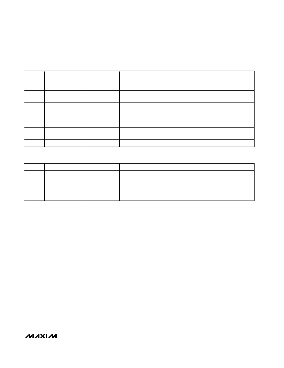
Table 7. Temperature Configuration Register (Address 4Bh, Power-Up Default = 00h)
Table 6. Interrupt Mask Register (Address 43h, Power-Up Default = 00h)
BIT
NAME
READ/WRITE
DESCRIPTION
0
2.5V
R/W
Setting the bit to 1 disables the Interrupt Status Register bit (bit 0) and the
ALERT output for the 2.5V
IN
input.
1
1.8V
R/W
Setting the bit to 1 disables the Interrupt Status Register bit (bit 1) and the
ALERT output for the 1.8V
IN
input.
2
5V
R/W
Setting the bit to 1 disables the Interrupt Status Register bit (bit 2) and the
ALERT output for the 5V
IN
input.
3
3.3V
R/W
Setting the bit to 1 disables the Interrupt Status Register bit (bit 3) and the
ALERT output for the V
CC
input.
4
Temp.
R/W
Setting the bit to 1 disables the Interrupt Status Register bit (bit 4) and the
ALERT output for temperature.
5, 6, 7
Reserved
—
—
BIT
NAME
READ/WRITE
DESCRIPTION
0, 1
Hot Temperature
Interrupt Select
R/W
Bit 1, bit 0 = 00: Default mode
Bit 1, bit 0 = 01: One-time interrupt mode
Bit 1, bit 0 = 10: Comparator mode
Bit 1, bit 0 = 11: Default mode
2
−7
Reserved
—
—