Electrical characteristics (continued) – Rainbow Electronics MAX6683 User Manual
Page 3
MAX6683
Temperature Sensor and System Monitor
in a 10-Pin µMAX
_______________________________________________________________________________________
3
Note 1: Total monitoring time includes temperature conversion and four analog input voltage conversions.
Note 2: A master device must provide at least a 300ns hold time for the SDA signal, referred to V
IL
of the SCL signal, to bridge the
undefined region of SCL’s falling edge.
Note 3: C
b
= total capacitance of one bus line in pF. Rise and fall times are measured between 0.3
✕
V
CC
to 0.7
✕
V
CC
.
Note 4: Input filters on SDA, SCL, and ADD suppress noise spikes <50ns.
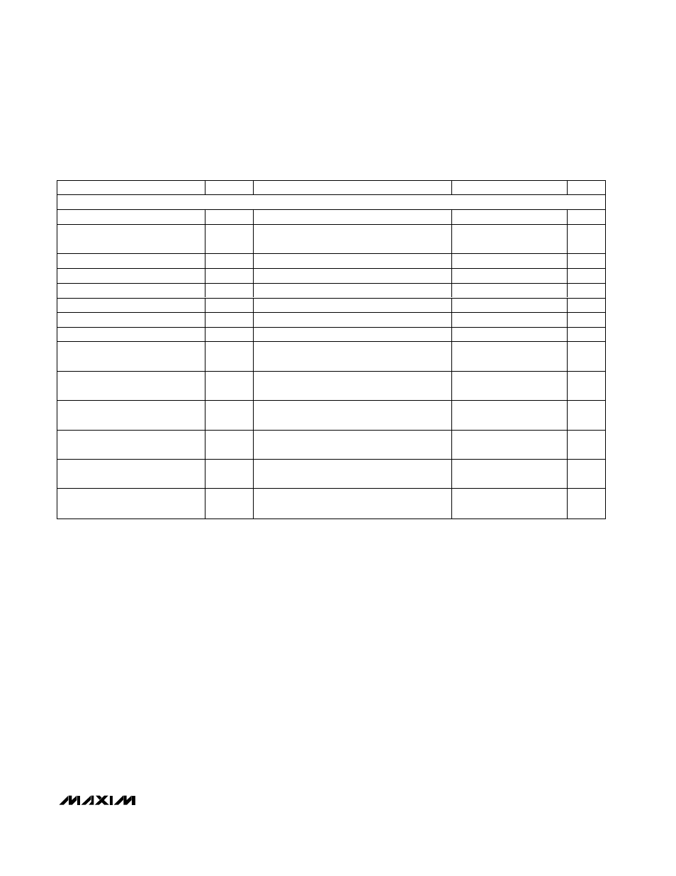
ELECTRICAL CHARACTERISTICS (continued)
(T
A
= -40°C to +125°C, unless otherwise noted. Typical values are at V
CC
= +3.3V, T
A
= +25°C.)
PARAMETER
SYMBOL
CONDITIONS
MIN
TYP
MAX
UNITS
TIMING (Figures 3 and 4)
Serial Clock Frequency
f
SCL
0
400
kHz
Bus Free Time Between Stop
and Start
T
BUF
1.3
µs
Start Condition Hold Time
t
HD
:
STA
0.6
µs
Stop Condition Hold Time
t
SU
:
STO
0.6
µs
Clock Low Time
T
LOW
1.3
µs
Clock High Time
T
HIGH
0.6
µs
Data Setup Time
t
SU
:
DAT
100
ns
Data Hold Time
t
HD
:
DAT
(Note 2)
0
0.9
µs
Receive SCL/SDA Minimum
Rise Time
t
R
(Note 3)
20 +
0.1C
b
ns
Receive SCL/SDA Maximum
Rise Time
t
R
(Note 3)
300
ns
Receive SCL/SDA Minimum Fall
Time
t
F
(Note 3)
20 +
0.1C
b
ns
Receive SCL/SDA Maximum Fall
Time
t
F
(Note 3)
300
ns
Transmit SDA Fall Time
t
F
C
b
= 400pF, I
SINK
= 3mA
20 +
0.1C
b
300
ns
Pulse Width of Spike
Suppressed
t
SP
(Note 4)
50
ns