Rainbow Electronics MAX66100 User Manual
Page 3
MAX66100
ISO 15693-Compliant 64-Bit UID
_______________________________________________________________________________________
3
AVAILABLE COMMANDS:
DATA FIELD AFFECTED:
INVENTORY
STAY QUIET
SELECT
RESET TO READY
UID, AFI, DSFID, ADMINISTRATIVE DATA
UID
UID
UID
NETWORK
FUNCTION COMMANDS
GET SYSTEM INFORMATION
UID, AFI, DSFID, CONSTANTS
MEMORY FUNCTION
COMMANDS
COMMAND TYPE:
MAX66100
Figure 2. ISO 15693 Commands Overview
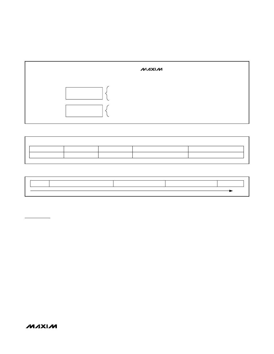
MSb
LSb
64
57 56
49 48
45 44
37 36
1
E0h
2Bh
0h
FEATURE CODE (01h)
36-BIT IC SERIAL NUMBER
Figure 3. 64-Bit UID
SOF
1 OR MORE DATA BYTES
CRC (LSB)
CRC (MSB)
EOF
TIME
Figure 4. ISO 15693 Frame Format
ISO 15693 Communication
Concept
The communication between the master and the
MAX66100 (slave) is based on the exchange of data
packets. The master initiates every transaction; only
one side (master or slaves) transmits information at any
time. Each data packet begins with a start-of-frame
(SOF) pattern and ends with an end-of-frame (EOF)
pattern. A data packet with at least 3 bytes between
SOF and EOF is called a frame (Figure 4). The last 2
bytes of an ISO 15693 frame are an inverted 16-bit
CRC of the preceding data generated according to the
CRC-16-CCITT polynomial. This CRC is transmitted with
the LSB first. For more details on the CRC-16-CCITT,
refer to ISO 15693 Part 3, Annex C.
For transmission, the frame information is modulated on
a carrier frequency, which is 13.56MHz for ISO 15693.
The subsequent paragraphs are a concise description
of the required modulation and coding. For full details
including graphics of the data coding schemes and
SOF/EOF timing, refer to ISO 15693-2, Sections 7.2,
7.3, and 8.
The path from master to slave uses amplitude modu-
lation (Figure 5); the modulation index can be either in
the range of 10% to 30% or 100% (ISO 15693-2,
Section 7.1). The standard defines two pulse-position
coding schemes that must be supported by a compli-
ant device. Scheme A uses the “1 out of 256” method
(Figure 6), where the transmission of 1 byte takes
4.833ms, equivalent to a data rate of 1655bps. The
location of a modulation notch during the 4.833ms con-
veys the value of the byte. Scheme B uses the “1 out of
4” method (Figure 7), where the transmission of 2 bits
takes 75.52µs, equivalent to a data rate of 26,484bps.
The location of a modulation notch during the 75.52µs
conveys the value of the 2 bits. A byte is transmitted as
a concatenation of four 2-bit transmissions, with the
least significant 2 bits of the byte being transmitted
first. The transmission of the SOF pattern takes the
same time as transmitting 2 bits in Scheme B. The SOF
pattern has two modulation notches, which makes it