Electrical characteristics – Rainbow Electronics ADC10738 User Manual
Page 7
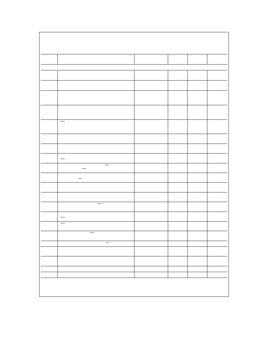
Electrical Characteristics
(Continued)
The following specifications apply for V
a
e
AV
a
e
DV
a
e a
5 0 V
DC
V
REF
a
e
2 5 V
DC
V
REF
b
e
GND V
IN
b
e
2 5V for
Signed Characteristics V
IN
b
e
GND for Unsigned Characteristics and f
CLK
e
2 5 MHz unless otherwise specified Boldface
limits apply for T
A
e
T
J
e
T
MIN
to T
MAX
all other limits T
A
e
T
J
e a
25 C (Note 16)
Symbol
Parameter
Conditions
Typical
Limits
Units
(Note 11)
(Note 12)
(Limits)
AC CHARACTERISTICS
f
CLK
Clock Frequency
3 0
2 5
MHz(max)
5
kHz(min)
Clock Duty Cycle
40
%(min)
60
%(max)
t
C
Conversion Time
12
12
Clock
Cycles
5
5
m
s(max)
t
A
Acquisition Time
4 5
4 5
Clock
Cycles
2
2
m
s(max)
t
SCS
CS Set-Up Time Set-Up Time from Falling Edge of
14
30
ns(min)
CS to Rising Edge of Clock
(1 t
CLK
(1 t
CLK
(max)
b
14 ns)
b
30 ns)
t
SDI
DI Set-Up Time Set-Up Time from Data Valid on
16
25
ns(min)
DI to Rising Edge of Clock
t
HDI
DI Hold Time Hold Time of DI Data from Rising
2
25
ns(min)
Edge of Clock to Data not Valid on DI
t
AT
DO Access Time from Rising Edge of CLK When
30
50
ns(min)
CS is ‘‘Low’’ during a Conversion
t
AC
DO or SARS Access Time from CS Delay from
30
70
ns(max)
Falling Edge of CS to Data Valid on DO or SARS
t
DSARS
Delay from Rising Edge of Clock to Falling Edge of
100
200
ns(max)
SARS when CS is ‘‘Low’’
t
HDO
DO Hold Time Hold Time of Data on DO after
20
35
ns(max)
Falling Edge of Clock
t
AD
DO Access Time from Clock Delay from Falling
40
80
ns(max)
Edge of Clock to Valid Data of DO
t
1H
t
0H
Delay from Rising Edge of CS to DO or SARS
40
50
ns(max)
TRI-STATE
t
DCS
Delay from Falling Edge of Clock to Falling Edge of
20
30
ns(min)
CS
t
CS(H)
CS ‘‘HIGH’’ Time for A D Reset after Reading of
1 CLK
1 CLK
cycle(min)
Conversion Result
t
CS(L)
ADC10731 Minimum CS ‘‘Low’’ Time to Start a
1 CLK
1 CLK
cycle(min)
Conversion
t
SC
Time from End of Conversion to CS Going ‘‘Low’’
5 CLK
5 CLK
cycle(min)
t
PD
Delay from Power-Down command to 10% of
1
m
s
Operating Current
t
PC
Delay from Power-Up Command to Ready to Start
10
m
s
a New Conversion
C
IN
Capacitance of Logic Inputs
7
pF
C
OUT
Capacitance of Logic Outputs
12
pF
7