Detailed description – Rainbow Electronics MAX5144 User Manual
Page 7
MAX5141–MAX5144
+3V/+5V, Serial-Input,
Voltage-Output, 14-Bit DACs
_______________________________________________________________________________________
7
Detailed Description
The MAX5141–MAX5144 voltage-output, 14-bit digital-
to-analog converters (DACs) offer full 14-bit perfor-
mance with less than 1LSB integral linearity error and
less than 1LSB differential linearity error, thus ensuring
monotonic performance. Serial data transfer minimizes
the number of package pins required.
The MAX5141–MAX5144 are composed of two
matched DAC sections, with a 10-bit inverted R-2R
DAC forming the ten LSBs and the four MSBs derived
from 15 identically matched resistors. This architecture
allows the lowest glitch energy to be transferred to the
DAC output on major-carry transitions. It also lowers the
DAC output impedance by a factor of eight compared
MAX5142
MAX5144
MAX400
GND
(GND)
V
DD
R
INV
R
FB
RFB
INV
OUT
CLR
SCLK
DIN
CS
0.1
µF
+3V/+5V
EXTERNAL OP AMP
MC68XXXX
PCS0
MOSI
SCLK
IC1
BIPOLAR
OUT
+5V
-5V
0.1
µF
+2.5V
1
µF
MAX6166
REF
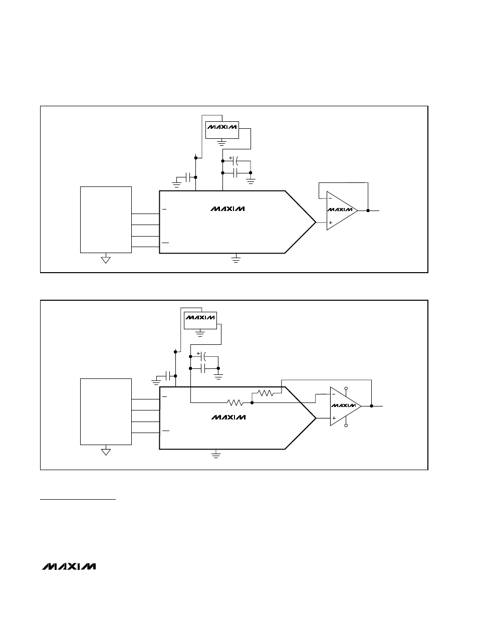
Figure 2b. Typical Operating Circuit—Bipolar Output
MAX5141
MAX5142
MAX5143
MAX5144
MAX495
(GND)
V
DD
REF
OUT
SCLK
DIN
CS
GND
0.1
µF
0.1
µF
+2.5V
EXTERNAL OP AMP
MC68XXXX
PCS0
MOSI
SCLK
UNIPOLAR
OUT
CLR
1
µF
IC1
MAX6166
+3V/+5V
Figure 2a. Typical Operating Circuit—Unipolar Output