Rainbow Electronics MAX16915 User Manual
Page 7
Ideal Diode, Reverse-Battery, and Overvoltage Protection
Switch/Limiter Controllers with External MOSFETs
MAX16914/MAX16915
_______________________________________________________________________________________ 7
Overvoltage Limiter
Controller (MAX16915)
In the MAX16915, TERM is internally connected to
SENSE OUT (see the Functional Diagram) allowing the
IC to operate in voltage-limiter mode.
During normal operation, GATE2 is pulled low to fully
enhance the MOSFET. The external MOSFET’s drain
voltage is monitored through a resistor-divider between
TERM, SET, and GND. When the output voltage rises
above the adjusted overvoltage threshold, an internal
comparator pulls GATE2 to V
CC
turning off P2. When
the monitored voltage goes below the overvoltage
threshold (-4% hysteresis), the p-channel MOSFET (P2)
is turned on again. During a continuous overvoltage
condition, MOSFET (P2) cycles on and off (between the
overvoltage threshold and the hysteresis), generating a
sawtooth waveform with a frequency dependent on the
load capacitance and load current. This process contin-
ues to keep the voltage at the output regulated to within
approximately a 4% window. The output voltage is regu-
lated during the overvoltage transients and MOSFET
(P2) continues to conduct during the overvoltage event,
operating in switched-linear mode.
Caution must be exercised when operating the
MAX16915 in voltage-limiting mode for long durations
due to the MOSFET’s power-dissipation consideration
(see the MOSFET Selection section).
Shutdown
The MAX16914/MAX16915 feature an active-low shut-
down input (SHDN). Drive SHDN low to switch off FET
(P2), disconnecting the input from the output, thus
placing the IC in low-quiescent-current mode. Reverse-
battery protection is still maintained.
Reverse-Battery Protection
The MAX16914/MAX16915 feature reverse-battery pro-
tection to prevent damage to the downstream circuitry
caused by battery reversal or negative transients. The
reverse-battery protection blocks the flow of current into
the downstream load and allows the circuit designer to
remove series-protection diodes.
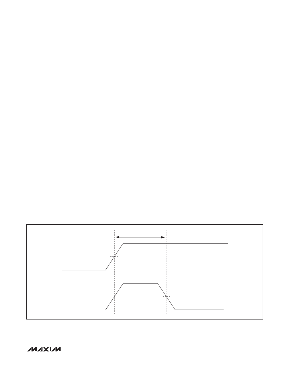
Back-Charge Switch-Off
The MAX16914/MAX16915 monitor the input-to-output
differential voltage between SENSE IN and SENSE OUT.
It turns off the external FET (P1) when (V
SENSE OUT
-
V
SENSE IN
) > 25mV (see Figure 1) to prevent discharg-
ing of a downstream tank capacitor into the battery sup-
ply during an input voltage drop, such as a cold-crank
condition or during a superimposed sinusoidal voltage
on top of the supply voltage. It turns on the FET (P1)
again if the back-charge voltage threshold hysteresis of
50mV is satisfied.
Figure 1. Back-Charge Turn-Off Time
I
OUT
V
OUT
- V
BATT
= 0V
V
OUT
- V
BATT
= 50mV
t
BC
= 10µs (max)
V
BATT
= 9V
50% (25mV)
50%