Detailed description, Functional diagram – Rainbow Electronics MAX16915 User Manual
Page 6
Ideal Diode, Reverse-Battery, and Overvoltage Protection
Switch/Limiter Controllers with External MOSFETs
MAX16914/MAX16915
6 ______________________________________________________________________________________
Detailed Description
The MAX16914/MAX16915 are ultra-small, low-quies-
cent, high load-current, overvoltage-protection circuits
for automotive or industrial applications. These devices
monitor the input and output voltages and control two
p-channel MOSFETs to protect downstream loads from
reverse-battery, overvoltage, and high-voltage transient
conditions and prevent downstream tank capacitors
from discharging into the source (back-charging).
One MOSFET (P1) eliminates the need for external
diodes, thus minimizing the input voltage drop and
provides back-charge and reverse-battery protection.
The second MOSFET (P2) isolates the load or regulates
the output voltage during an overvoltage condition.
These ICs allow system designers to size the external
p-channel MOSFET to their load current, voltage drop,
and board size.
Overvoltage Switch-Off Controller
(MAX16914)
In the MAX16914, the input voltage is monitored (TERM
is internally shorted to V
CC
—see the Functional Diagram)
making the device an overvoltage switch-off controller.
As the V
CC
voltage rises, and the programmed overvolt-
age threshold is tripped, the internal fast comparator
turns off the external p-channel MOSFET (P2), pulling
GATE2 to V
CC
to disconnect the power source from
the load. When the monitored voltage goes below the
adjusted overvoltage threshold, the MAX16914 enhanc-
es GATE2, reconnecting the load to the power source.
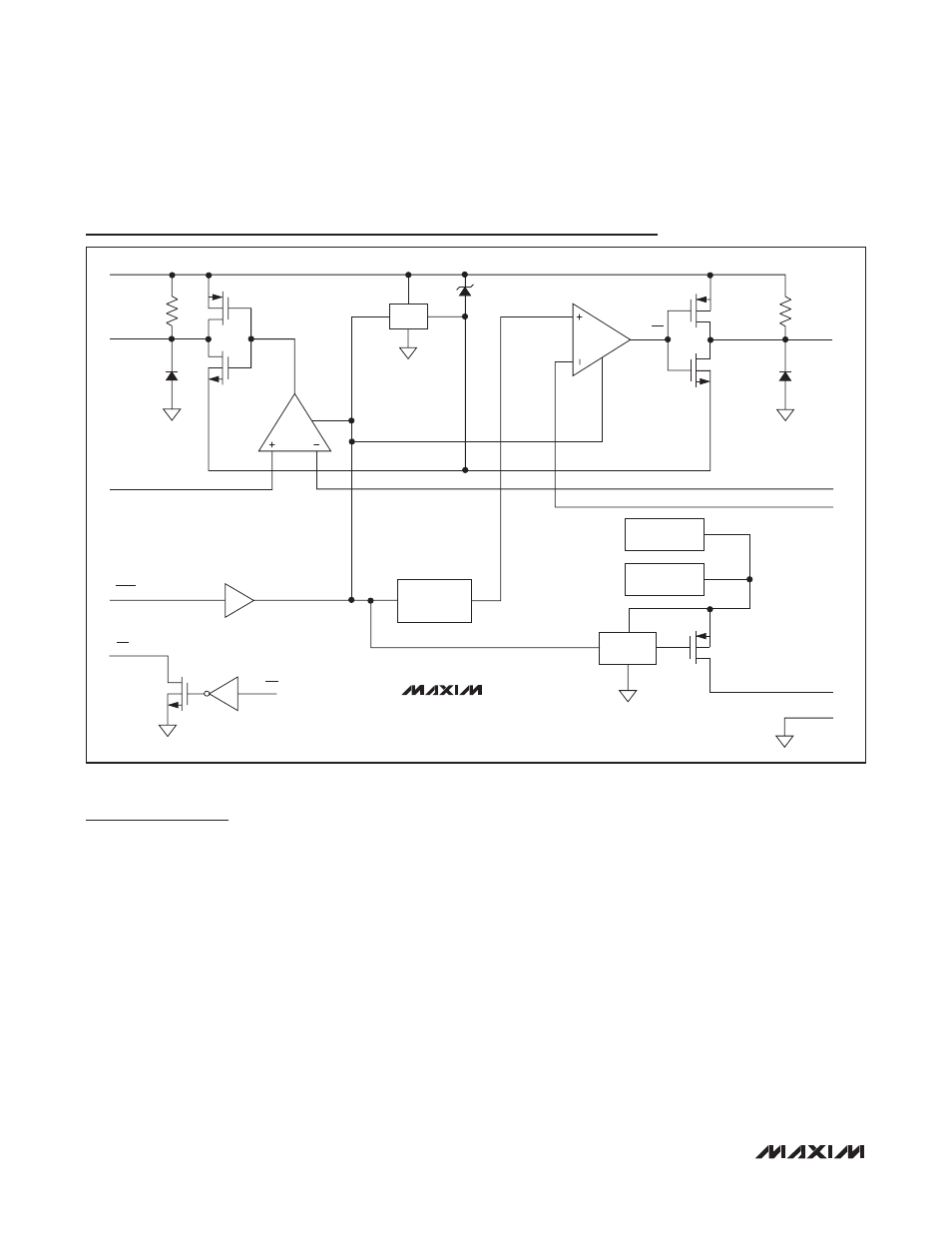
Functional Diagram
REG
GATE2
1.20V
GATE1
SENSE IN
SHDN
OV
V
CC
SENSE OUT
SET
TERM
GND
TERM
SWITCH
TO V
CC
FOR
MAX16914
TO SENSE OUT
FOR MAX16915
BANDGAP
BIAS
OV1
OV1
MAX16914
MAX16915