Rainbow Electronics MAX4074_MAX4078 User Manual
Page 10
MAX4074–MAX4078
Micropower, SOT23, Rail-to-Rail,
Fixed-Gain, GainAmp/Open-Loop Op Amps
10
______________________________________________________________________________________
Pin Description
_______________Detailed Description
Maxim’s GainAmp fixed-gain amplifiers combine a low-
cost rail-to-rail op amp with internal gain-setting resis-
tors. Factory-trimmed on-chip resistors provide 0.1%
gain accuracy while decreasing design size, cost, and
layout. There are two versions in this amplifier family:
single/dual/quad open-loop, unity-gain-stable devices
(MAX4076/MAX4077/MAX4078), and single/dual fixed-
gain devices (MAX4074/MAX4075). All amplifiers fea-
ture rail-to-rail outputs and drive a 10k
Ω load while
maintaining excellent DC accuracy.
Open-Loop Op Amps
The single/dual/quad MAX4076/MAX4077/MAX4078 are
low-power, open-loop op amps with rail-to-rail outputs.
These devices are compensated for unity-gain stability
and feature a GBW product of 230kHz. The common-
mode range extends from 150mV below the negative
rail to within 1.2V of the positive rail. These high-perfor-
mance op amps serve as the core for this family of
GainAmp fixed-gain amplifiers. Although the -3dB band-
width will not correspond to that of a fixed-gain amplifier
in higher gain configurations, these open-loop op amps
can be used to prototype designs.
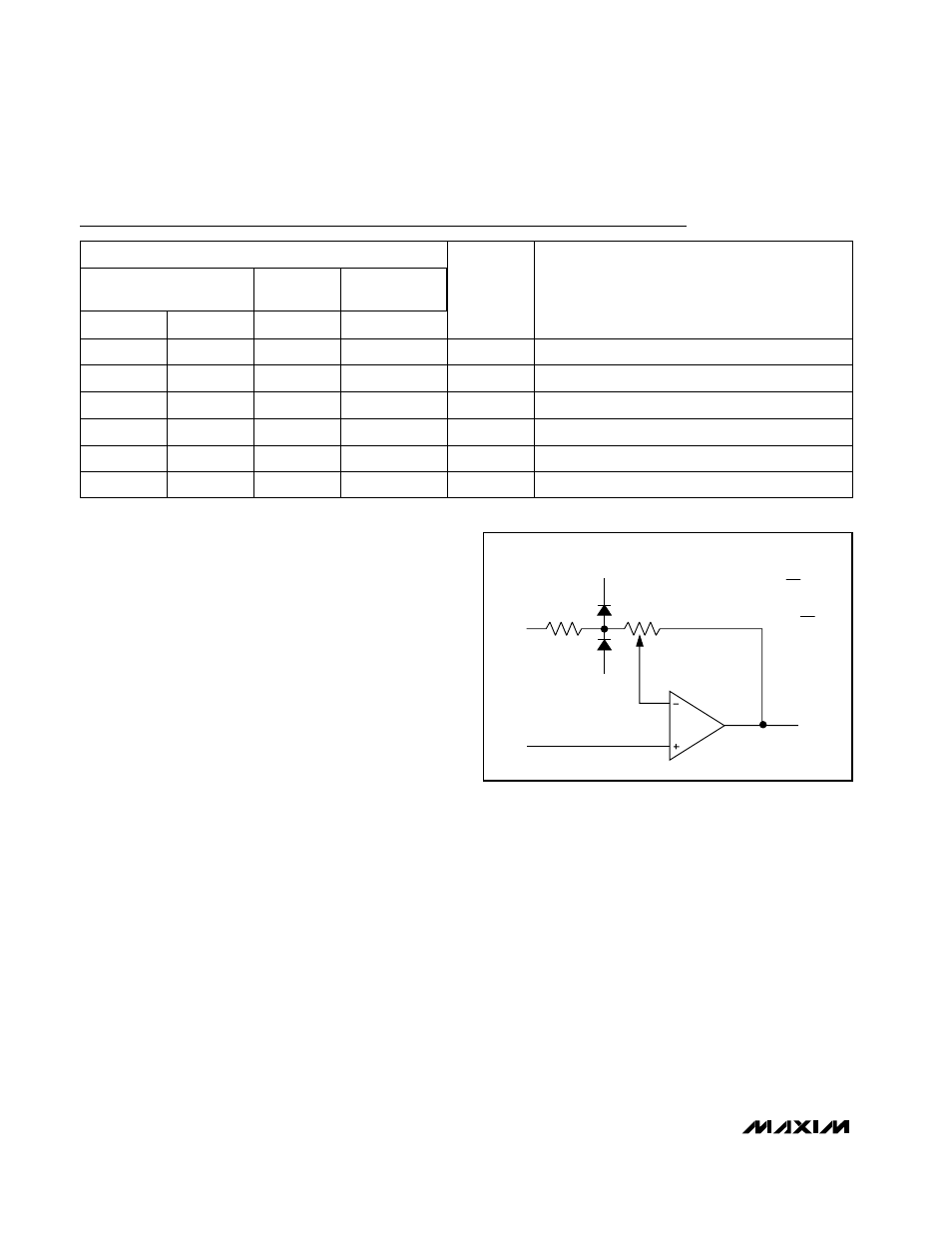
Internal Gain-Setting Resistors
Maxim’s proprietary laser trimming techniques allow
R
F
/R
G
values (Figure 1) that produce many different
gain configurations. These GainAmp fixed-gain ampli-
fiers feature a negative-feedback resistor network that
is laser trimmed to provide a gain-setting feedback
ratio (R
F
/R
G
) with 0.1% typical accuracy. The standard
op amp pinouts allow the GainAmp fixed-gain ampli-
fiers to plug directly into existing board designs, easily
replacing op amps-plus-resistor gain blocks.
OUT
A
V
=
-R
F
R
G
R
G
R
F
IN-
IN+
V
CC
V
EE
A
V
= 1 +
R
F
R
G
Figure 1. Internal Gain-Setting Resistors
FUNCTION
Positive Supply
V
CC
5
No Connection. Not internally connected.
N.C.
—
Inverting Amplifier Input
IN_-
4
Noninverting Amplifier Input
IN_+
3
Negative Supply or Ground
V
EE
2
Amplifier Output
OUT_
1
7
1, 5, 8
2
3
4
6
8
—
2, 6
3, 5
4
1, 7
4
—
2, 6, 9, 13
3, 5, 10, 12
11
1, 7, 8, 14
MAX4075
MAX4077
MAX4078
µMAX/SO
SO/TSSOP
SOT23
NAME
SO
PIN
MAX4074/MAX4076