Electrical characteristics (continued) – Rainbow Electronics MAX9758 User Manual
Page 5
MAX9756/MAX9757/MAX9758
2.3W Stereo Speaker Amplifiers and DirectDrive
Headphone Amplifiers with Automatic Level Control
_______________________________________________________________________________________
5
Note 1:
All devices are 100% production tested at room temperature. All temperature limits are guaranteed by design.
Note 2:
PSRR is specified with the amplifier input connected to GND through R
IN
and C
IN
.
Note 3:
Output power levels are measured with the TQFN’s exposed paddle soldered to the ground plane.
Note 4:
Speaker path gain is defined as: A
VSPKR
= (V
OUT+
- V
OUT-
)/V
IN__
).
Note 5:
Speaker mode testing performed with 8
Ω resistive load connected across BTL output. Headphone mode testing per-
formed with 32
Ω resistive load connected between HP_ and GND. Mode transitions are controlled by SHDN.
Note 6:
Headphone path gain is defined as: A
VHP
= V
HP_
/V
IN__
.
Note 7:
See Table 3 for detains on the mute levels.
Note 8:
Attack envelope is exponential. Attack time is defined as the 15 x 10
3
x C
T
.
Note 9:
Time for the gain to return to within 10% of nominal gain setting after the input signal has fallen below the PREF threshold.
Release is linear in dB. Release time is proportional to magnitude of gain compression.
Note 10: Dropout voltage is defined as (V
IN
- V
OUT
) when V
OUT
is 2% below the value of V
OUT
for V
IN
= V
OUT(NOM)
+ 1V.
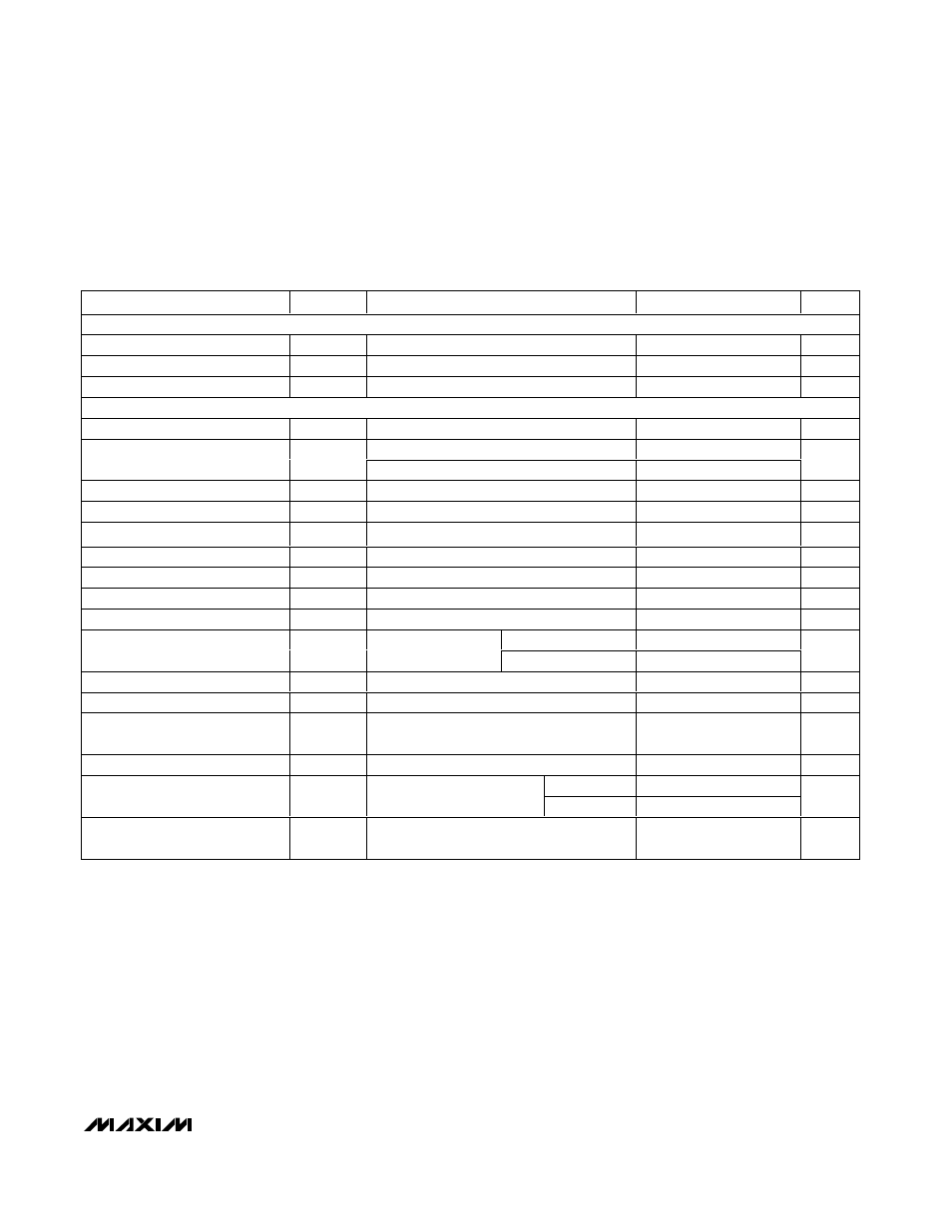
ELECTRICAL CHARACTERISTICS (continued)
(V
DD
= PV
DD
= HPV
DD
= CPV
DD
= IN = +5.0V, GND = PGND = CPGND = 0,
SHDN = V
DD
, REGEN = V
DD
, DR = SET = GND, C
BIAS
= 1µF, C
PVSS
= 1µF, C1 = C2 = 1µF, PREF = unconnected, speaker loads terminated between OUT_+ and OUT_-, headphone load
terminated between HP_ and GND, GAIN1 = GAIN2 = GAIN3 = VOL = 0 (A
V(SP)
= 15dB, A
V(HP)
= 0dB), T
A
= -40°C to +85°C, unless
otherwise noted. Typical values are at T
A
= +25°C.) (Note 1)
PARAMETER
SYMBOL
CONDITIONS
MIN
TYP
MAX
UNITS
LOGIC INPUT HEADPHONE (HPS)
Input High Voltage
V
IH
2
V
Input Low Voltage
V
IL
0.8
V
HPS Pullup Current
35
µA
LOW-DROPOUT LINEAR REGULATOR
Input Voltage Range
V
IN
Inferred from line regulation
3.5
5.5
V
I
OUT
= 0mA,
SHDN = GND
100
160
Supply (Ground) Current
I
Q
I
OUT
= 150mA
350
µA
Shutdown Current
I
SHDN
REGEN = 0V
0.1
3
µA
Output Current
I
OUT
150
mA
Fixed Output Voltage Accuracy
I
OUT
= 1mA
±1.5
%
Adjustable Output Voltage Range
V
SET
4.85
V
SET Reference Voltage
V
SET
1.19
1.21
1.23
V
SET Dual-Mode Threshold
200
mV
SET Input Leakage Current
I
SET
±20
±500
nA
I
OUT
= 50mA
25
50
Dropout Voltage (Note 10)
ΔV
OD
V
OUT
= 4.65V (fixed
output operation)
I
OUT
= 150mA
100
150
mV
Output Current Limit
I
LIM
300
mA
Startup Time
20
µs
Line Regulation
V
IN
= 3.5V to 5.5V, V
OUT
= 2.5V,
I
OUT
= 1mA
-0.1
+0.01
+0.1
%/V
Load Regulation
V
OUT
= 4.65V, 1mA < I
OUT
< 150mA
0.5
%
f = 1kHz
60
Ripple Rejection
V
RIPPLE
= 200mV
P-P
f = 10kHz
50
dB
Output Voltage Noise
20Hz to 22kHz, C
OUT
= 2 x 1µF,
I
OUT
= 150mA, V
OUT
= 4.65V
100
µV
RMS