Pin description (continued) – Rainbow Electronics MAX9758 User Manual
Page 12
MAX9756/MAX9757/MAX9758
2.3W Stereo Speaker Amplifiers and DirectDrive
Headphone Amplifiers with Automatic Level Control
12
______________________________________________________________________________________
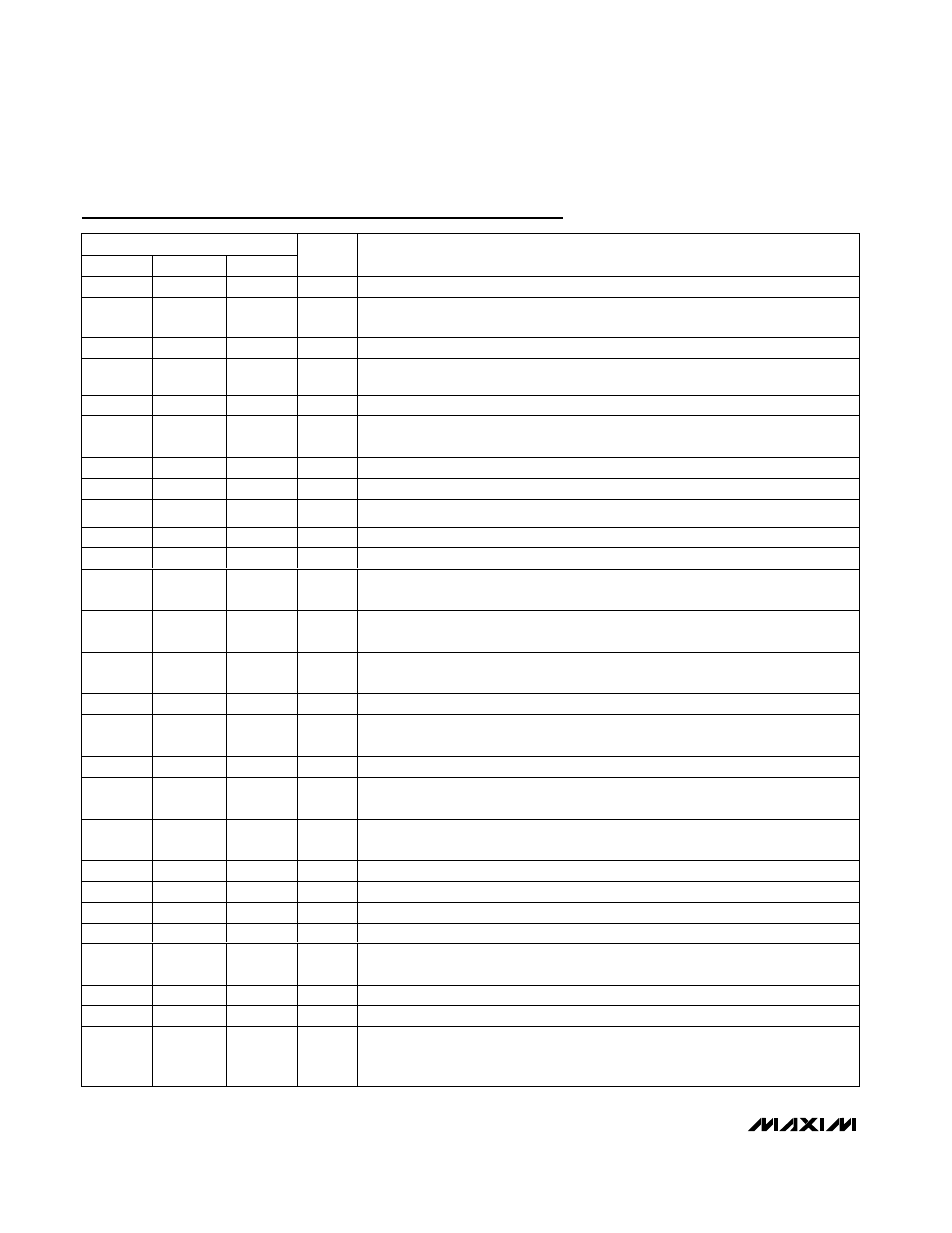
Pin Description (continued)
PIN
MAX9756
MAX9757
MAX9758
NAME
FUNCTION
10
9
9
CPV
DD
Charge-Pump Power Supply. Bypass with 1µF ceramic capacitor to CPGND.
11
10
10
C1P
Charge-Pump Flying-Capacitor Positive Terminal. Connect a 1µF capacitor from C1P
to C1N.
12
11
11
CPGND
Charge-Pump Ground
13
12
12
C1N
Charge-Pump Flying-Capacitor Negative Terminal. Connect a 1µF capacitor from
C1P to C1N.
14
13
13
CPV
SS
Charge-Pump Negative Output. Connect to V
SS
.
15
14
14
V
SS
Headphone Amplifier Negative Power Supply. Bypass with 1µF ceramic capacitor to
GND.
16
15
15
HPR
Right Headphone Output
17
16
16
HPL
Left Headphone Output
18
17
17
HPV
DD
Headphone Positive Power Supply. Bypass with 1µF ceramic capacitor to GND.
20
19
19
OUTR-
Right-Channel Negative Speaker Output
21
20
20
OUTR+
Right-Channel Positive Speaker Output
23
22
22
HPS
H ead p hone S ense Inp ut. Leave H P S unconnected i f autom ati c head p hone sensi ng
i s not used .
24
—
23
REGEN
LD O E nab l e. C onnect RE GE N to V
D D
to enab l e the LD O. C onnect to G N D to
d i sab l e LD O.
25
23
—
DR
Automatic Level Control Attack to Release Time Ratio Select. Hardwired to V
DD
,
GND, or BIAS to set the attack to release ratio; see the ALC section.
26
24
24
BIAS
Common-Mode Bias Voltage. Bypass with a 1.0µF capacitor to GND.
27
25
25
SHDN
Shutdown Input. Drive
SHDN low to disable the audio amplifiers. Connect SHDN to
V
DD
for normal operation.
28
26
26
VOL
Analog Volume Control Input
29
27
—
PREF
P ow er - Li m i ti ng Inp ut. C onnect a r esi stor fr om P RE F to G N D to set the sp eaker outp ut
cl am p i ng l evel . Leave P RE F unconnected to d i sab l e ALC ; see the ALC secti on.
30
—
27
SET
Regulator Feedback Input. Connect to GND for 4.65V fixed output. Connect to
resistor-divider for adjustable output; see the Low-Dropout Linear Regulator section.
31
28
28
GND
Ground
32
29
—
V
DD
Power Supply
33
—
—
IN
LDO Input. Bypass with two 1µF ceramic capacitors to GND.
34
—
30
OUT
LDO Output. Bypass with two 1µF ceramic capacitors to GND.
35
30
—
CT
Automatic Level Control Attack and Release Timing Capacitor. Connect CT to GND
to disable ALC; see the ALC section.
36
31
31
INR
Right-Channel Audio Input
—
—
29
V
DD
Power-Supply and LDO Input. Bypass with two 1µF ceramic capacitors to GND.
EP
EP
EP
EP
Exposed Pad. The external pad lowers the package’s thermal impedance by
providing a direct-heat conduction path from the die to the PC board. Connect the
exposed thermal pad to GND.