Rainbow Electronics MAX5362 User Manual
Page 10
MAX5360/MAX5361/MAX5362
the DAC data (6 bits + 2 subbits), and finally, a STOP
condition (Figure 6). The bus is then free for another
transmission.
SDA’s state is sampled, and therefore must remain sta-
ble while SCL is high. Data is transmitted in 8-bit bytes.
Nine clock cycles are required to transfer each byte to
the MAX5360/MAX5361/MAX5362. Release SDA during
the 9th clock cycle as the selected device acknowl-
edges the receipt of the byte, by pulling SDA low dur-
ing this time. A series resistor on the SDA line may be
needed if the master’s output is forced high while the
selected device acknowledges (Figure 4).
Slave Address
The MAX5360/MAX5361/MAX5362 are available with
one of four preset slave addresses. Each address
option is identified by the suffix L, M, N, or P added to
the part number. The address is defined as the 7 most
significant bits (MSBs) sent by the master after a
START condition. The address options are 0x60, 0x62,
0x64, and 0x66 (left justified with LSB set to 0). The 8th
bit, typically used to define a write or read protocol,
sets the device’s power mode (SHDN); the device is
powered down when SHDN is set to 1. During a device
search routine, the MAX5360/MAX5361/MAX5362
acknowledge both options (SHDN = 0 or SHDN = 1)
but does not change its power state if a stop condition
(or restart) is issued immediately. The second byte
(DAC data) must be sent/received for the device to
update both power mode and DAC output.
DAC Data
The 6-bit DAC data is decoded as straight binary MSB
first with 1LSB = (V
REF
/ 64) and converted into the cor-
responding analog voltage as shown in Table 1. Two
subbits complete the data byte; these 2 bits should be
set to zero since they are not tested to guaranteed-
monotonic performance.
After receiving the data byte, the MAX5360/MAX5361/
MAX5362 acknowledge its receipt and expect a STOP
condition, at which point the DAC output is updated.
The devices update the output and the power mode
only if the second byte is clocked in (SHDN = 0) or out
(SHDN = 1) of the device. When SHDN = 1, the master
will read all ones when clocking out a data byte. The
MAX5360/MAX5361/MAX5362 do not drive SDA except
for the acknowledge bit.
Low-Cost, Low-Power 6-Bit DACs with
2-Wire Serial Interface in SOT23 Package
10
______________________________________________________________________________________
SCL
SDA
START
CONDITION
STOP
CONDITION
1
3
2
4
6
5
7
9
8
10
12
11
13
15
14
16
18
17
ACK
LSB
MSB
LSB
MSB
0
1
1
0
X
0
X
ACK
SHDN
D6
D3
D4
D2
D0
D1
S1
S0
SLAVE ADDRESS BYTE
DAC CODE
Figure 6. Complete Serial Transmission
SCL
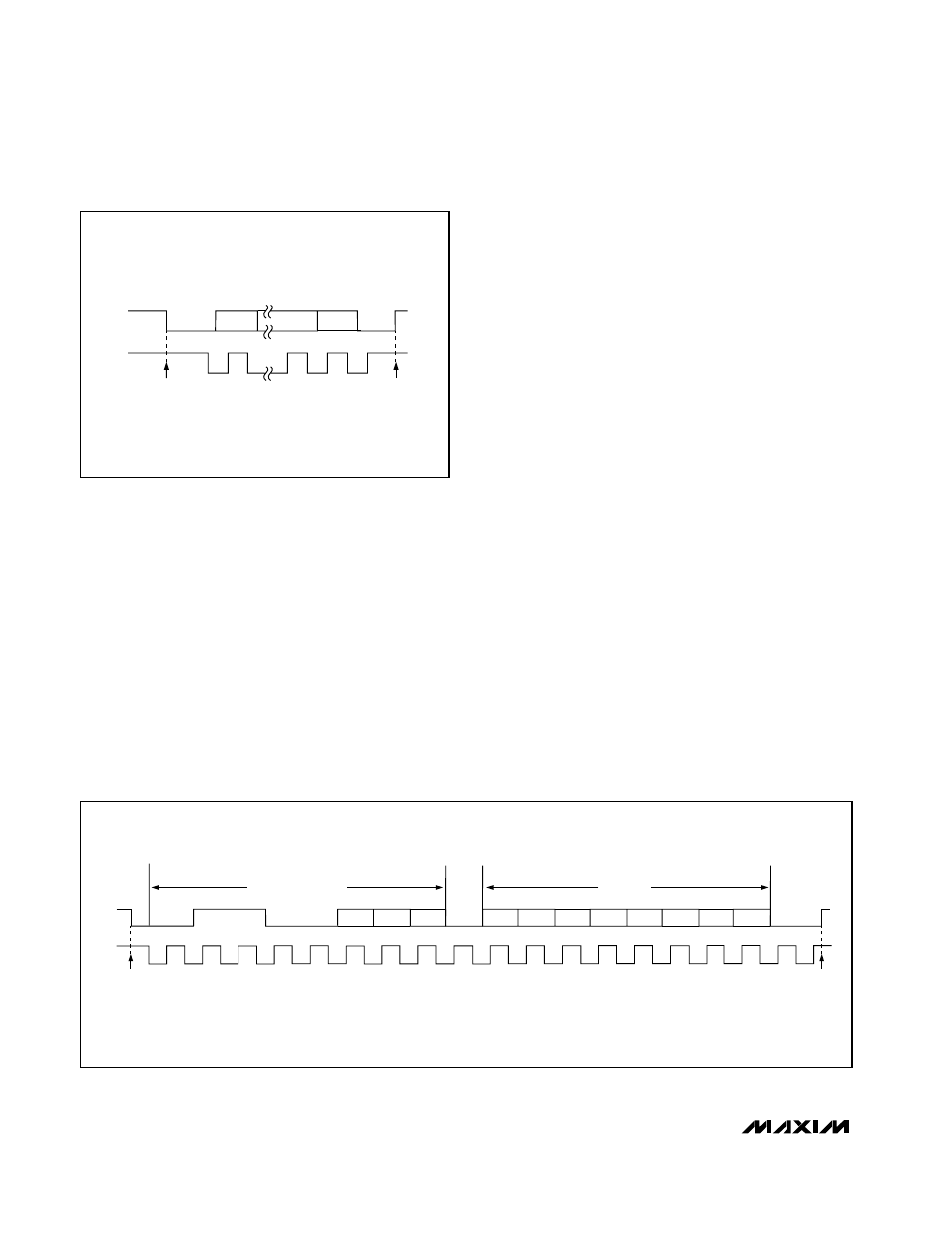
SDA
START CONDITION
STOP CONDITION
Figure 5. Start and Stop Conditions