Front panel operation, Routing, X-over – TC Electronic XO24 User Manual
Page 19
17
FRONT PANEL OPERATION
Routing
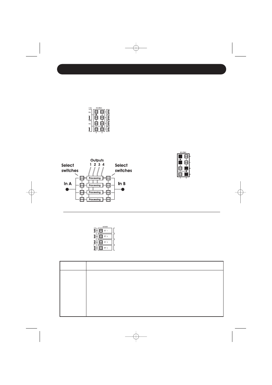
Routing section -as illustrated on the Front
panel
- alternative illustration of the Routing
section
The Routing section is the “railway-station” in
the signal chain. The signal present on Inputs
A/B can via the 2x4 select switches be routed
to none, any or all of the four Output channels.
From the Routing section out the four channels
are individually processed with separate X-
Over, EQ, Delay, Limiter and Output blocks.
Notice that the front panel layout is identical to
the actual signal flow through the unit.
Example:
Input A distributed to Output 1 and 2
Input B distributed to Output 3 and 4
A typical example of a stereo setup with split in
both sides.
More examples on pages 10 to 13.
X-Over A,B:
Type:
Gain
Freq:
Width/Slope:
X-Over
Hi Pass
N/A
20 Hz – 20 kHz
1st order
Lo Pass
Butterworth 2.
Butterworth 3.
Butterworth 4.
Bessel 2.
Bessel 3.
Bessel 4.
Linkw.Riley 2.
Linkw.Riley 4.
X-Over
For optimal settings please refer to your
speaker specifications.
The XO24 may hold presets that perfectly
match your speaker configuration.
XO24 US_3101.qxd 31-01-2005 10:59 Page 17