Operation – TC Electronic BMC-2 User Manual
Page 8
8
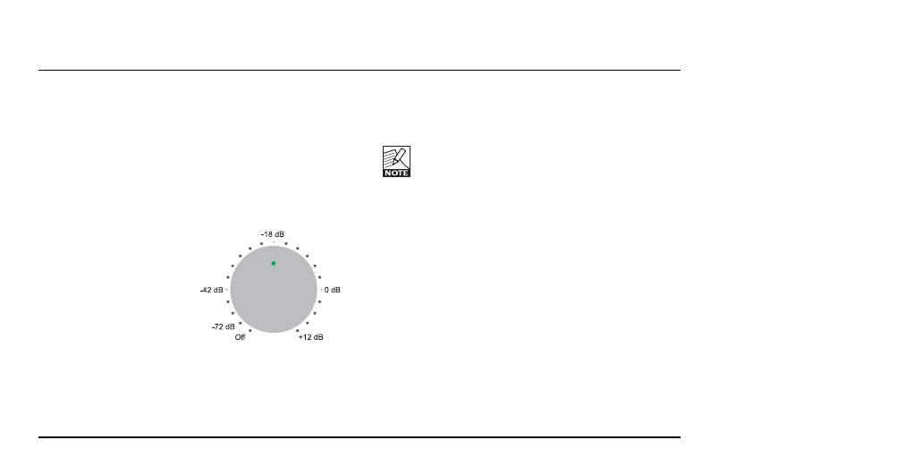
1 – Rotary Control
The Rotary Knob is always active, unless Ref Level or
Cut is enabled. The “Valid” LED and the dot in the
knob itself are lit when it is active.
The markings on the panel around the knob follow half
hour readings on a clock. According to these markings
the control has the following defined gain distribution:
Min:
Off
1st step:
-72 dB
9 o’clock:
-42 dB
(from here, each half hour
division equals 4 dB)
12 o’clock:
-18 dB
(from here, each half hour
division equals 3 dB)
3 o’clock:
0 dB
Max:
+12 dB
Every pot has a slightly different transfer function, so
the above numbers are guidelines only. A more precise
way of knowing the gain is to check the LED dot on the
knob, which briefly blinks at each 6 dB increment. This
blinking occurs when the gain is within +- 0.2 dB of a 6
dB increment.
To ensure a bit-transparent 0 dB setting (at 3
o’clock), the control “snaps” to 0.0 dB in a
slightly larger area around the 0 dB point.
Unless the ALT button is enabled, the Rotary Knob
controls the analog L/R monitor outputs. With ALT
selected, the analog outputs are muted, and the Rotary
Knob sets the output level of the digital output
assigned to ALT (see also section “7 – ALT”).
Per default, ALT uses the SPDIF/AES3 output.
2 – INPUT SELECT Buttons
The INPUT selectors determine which input source is
fed to the speakers, phones, coax S/PDIF, TOS and
ADAT outputs of the BMC-2.
When switching between synchronous input sources,
BMC-2 performs the operation as a cross-fade without
OPERATION