Operating instructions, Troubleshooting – Cobalt Digital COMPASS 9392 3G_HD_SD-SDI Dual-Channel Timecode Burn-In Inserter User Manual
Page 47
9392-TCB-OM (V1.3)
9392-TCB PRODUCT MANUAL
3-23
Operating Instructions
Troubleshooting
Table 3-3
Troubleshooting Processing Errors by Symptom
Symptom
Error/Condition
Corrective Action
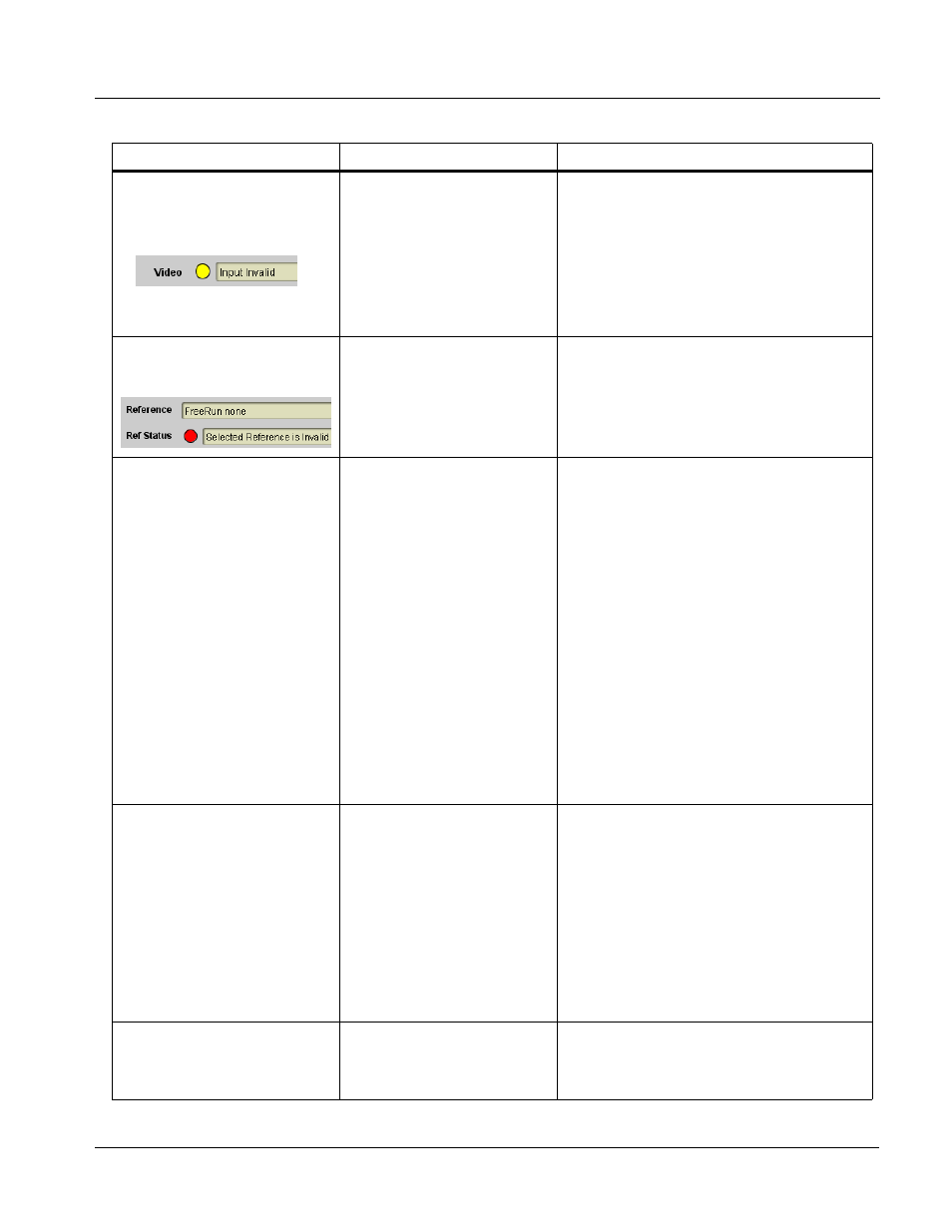
• DashBoard™ shows Video
yellow icon and Input Invalid
message in 9392 Card Info
pane.
• Card edge Input Format LEDs
show continuous cycling.
No video input present
Make certain intended video source is
connected to appropriate 9392 card video
input. Make certain BNC cable connections
between frame Rear I/O Module for the card
and signal source are OK.
• DashBoard™ shows invalid
in Ref Status message in 9392
Card Info pane.
Reference not properly
selected or not being received
(card has reverted to free-run
failover)
If external reference is not intended to be used,
make certain the Reference selection list is set
to appropriate alternate selection as desired.
Transient video or audio errors
(CRC, etc.) noted in viewing or
on logging waveform monitor.
Card reference cannot sync
with received video input.
Reference Selection control must be
appropriately set to match upstream video
signal timing:
• If input video is not locked to a frame
reference, the 9392 should be set to lock to
the respective input choice (SDI A or SDI B).
• If the video input is locked to a frame
reference, the 9392 should be set to lock to
the same reference (Reference 1 or
Reference 2).
Note: Both program video inputs must be of the
same refresh rate (e.g., 59.94 or 50, or
co-related (29.97 or 25), and
co-synchronous using frame sync or
similar means. In practical application,
both inputs should be
frame-synchronized using a common
frame reference, with the same
reference also to be used by this card.
RS-485 LTC not being locked on
to by card (yellow status
indicator)
• LTC RS-485 polarity
incorrect
• LTC RS-485 does not have
zero-crossing per RS-485
convention.
• Make certain RS-485 LTC connections are
as described in Connecting To 3-Wire
Phoenix Terminal Connectors (p. 2-5) in
Chapter 2, Installation and Setup.
• The RS-485 inputs received by the card must
have the customary zero-crossing associated
with RS-485. If the LTC source is offset
above or below ground (0 V), the sources
must be capacitively coupled or passed
through an analog audio DA that can restore
zero-crossing.
ERROR displayed on Timecode
Output Status.
Free-run selected as prioritized
manual selection, but timecode
generator is set to bypass
If free-run timecode is set as first prioritized
selection (i.e., free-run over any other choice),
Timecode Passthrough on Video Path >
Master Controls must be set to TC Gen On.