Moog Music MF-104M Analog Delay User Manual
Page 13
24
25
time to a musical fraction or multiple of the base time (MIDI note 60/C4
does not change the delay time).
Ex: C3 doubles the delay time (and pitches down any audio in the delay line
by an octave) and C5 halves the delay time (pitching any audio in the delay
line up by an octave).
DELAY TIME MULTIPLIER
The Delay Time Multiplier multiplies the delay time by 2, 4 or 8 vastly ex-
tending delay time. This feature is for obtaining unusual/lo-fi echo effects.
When the delay time is increased past the default maximum delay time
available on the front panel, the BBD Clock signal will be audible.
MIDI CLOCK SYNC
Both Delay Time and LFO Rate can be synchronized to MIDI System Real-
time Clock messages. These messages are 24 ppq messages that can be
sent via MIDI computer sequencers or from drum machines. To enable the
sending of these messages, consult the user manual for your MIDI device.
When the Analog Delay receives MIDI Clock messages, the corresponding
LED turns Orange to indicate that it is synchronized to the MIDI Clock tem-
po. When the LFO is synchronized to a MIDI Clock tempo, the LFO can be
set to divisions of this tempo. This is either from the front panel LFO Rate
control, or from MIDI CC# 107. Delay Time MIDI sync is enabled via CC# 89.
Note: Delay Time MIDI Clock Sync overrides MIDI Note Mode. If the Delay Time is syn-
chronized to MIDI Clock, then time changes due to MIDI Note Mode are ignored.
MIDI SYSEX MESSAGES
Used for updating or finding out the unit’s firmware version. For more
information about this, refer to user notes with any firmware updates
posted in the Analog Delay section of the Moog Music website.
CONTROL VOLTAGE INPUTS
•All CV input jacks are 1/4” tip-ring-sleeve phone jacks. The sleeve is
grounded and the ring terminals are supplied with +5 volts which is current-
limited. The tip terminals receive the variable voltages from the pedals.
•An expression pedal for use with the MF-104M should contain a 50K Ohm
or lower linear taper potentiometer.
•Applying a varying voltage to a pedal control input jack has the same
effect as turning the corresponding knob. With the panel controls set to
mid-position, a voltage control of about 5 volts is equal to turning the
corresponding knob through its entire range.
•Note that with the Analog Delay, you may use standard TS cables for
control voltages at the same time as Expression pedals.
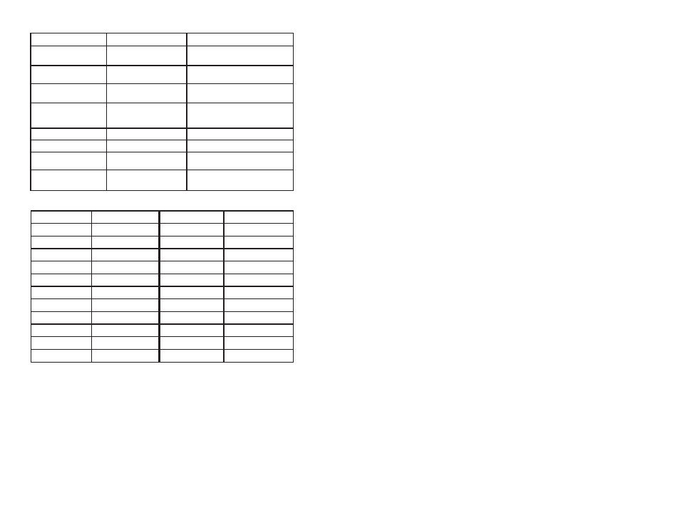
LFO CLOCK DIVISIONS (CC#71)
CC#71 VALUE
CLOCK DIVISION
CC#71 VALUE
CLOCK DIVISION
0-5
4 Whole
64-69
1/2 T
6-11
3 Whole
70-75
1/4
12-17
2 Whole
76-81
1/8 Dot
18-23
WH + 1/2 Dot
82-87
1/4 T
24-29
WH + 1/2
88-93
1/8
30-34
WH + 1/4
94-98
1/16 Dot
35-40
WH
99-104
1/8 T
41-46
1/2 Dot
105-110
1/16
47-52
WH T
111-116
1/16 T
53-58
1/2
117-122
1/32
59-63
1/4 Dot
123-127
1/32 T
MIDI NOTE MODES
The MF-104M delay time can be controlled from MIDI Note On messages.
When this mode is enabled the unit receives a MIDI “Note On” message.
The “Note ON” number determines the Delay time. The unit responds to
MIDI note numbers 0 to 90. The MIDI Note On Velocity value is ignored.
In Absolute mode each MIDI note corresponds to a delay time value. In
Relative mode, the delay base time is set by the Time knob, external CV,
or Time MIDI CC. MIDI notes higher or lower than C4 will change the delay
CC NUMBER
PARAMETER
VALUES
108
109
110
113
114
115
117
119
Enable LFO MIDI
Sync
Enable LFO Note
Reset
Enable MIDI Note
Spillover
MIDI Note Mode
MIDI Tap Tempo A
MIDI Tap Tempo B
Time/MIDI
LED Select
Enable Mod Wheel
to LFO Amount
0-63 = Disabled
64-127 = Enabled
0-63 = Disabled
64-127 = Enabled
0-63 = Disabled
64-127 = Enabled
0-41 = Off
42-83 = Absolute
84-127 = Relative
Any CC Value = a tap
(value > 63) = a tap
0-63 = Time LED
64-127 = MIDI LED
0-63 = Disabled
64-127 = Enabled