The mf-104m back panel – Moog Music MF-104M Analog Delay User Manual
Page 11
20
21
FEEDBACK - 1⁄4” TRS jack that can be used with a Moog EP-2 expression
pedal, or a 0V to +5V control voltage on a standard TS cable. A setting of
0 volts or ground allows for no feedback while a 5V setting gives infinite
feedback. To change the feedback amount from zero to infinite via control
voltage or expression pedal, set the
FEEDBACK control to 12:00 position.
TIME - 1⁄4” TRS jack that can be used with a Moog EP-2 expression pedal,
or a 0V to +5V control voltage on a standard TS cable. To change the
DE-
LAY TIME for a selected range from longest to shortest via control voltage
or expression pedal, set the
DELAY TIME control to 12:00 position.
LFO RATE - 1⁄4” TRS jack that can be used with a Moog EP-2 expression
pedal, or a 0V to +5V control voltage on a standard TS cable.
To use an expression pedal to modify the LFO Rate (0.05 Hz to 50 Hz) set
the
LFO RATE to 12:00 position. Rotate the LFO RATE knob counterclock-
wise. With a 0V control voltage applied to the LFO Rate CV input, the LFO
Rate can be reduced to half of the minimum panel rate. (.025 Hz) Now
rotate the
LFO RATE control fully Clockwise. With a +5V control voltage
applied to the LFO Rate CV input, the LFO Rate can be increased to double
the maximum panel rate. (100 Hz)
LFO AMOUNT - 1⁄4” TRS jack that can be used with a Moog EP-2 expres-
sion pedal, or a 0V to +5V control voltage on a standard TS cable. To
modify the
LFO AMOUNT from minimum to maximum via control voltage
or expression pedal, set the
LFO AMOUNT control to 12:00 position.
MIX - 1⁄4” TRS jack that can be used with a Moog EP-2 expression pedal,
or a 0V to +5V control voltage on a standard TS cable. To change the Mix
from dry to wet via control voltage or expression pedal set the
MIX control
to 12:00 position.
MIDI IN - Standard 5-pin DIN for receiving MIDI messages from another
MIDI device such as a MIDI controller or a sequencer. Refer to the MIDI sec-
tion of this manual for use of the Analog Delay with other MIDI devices.
POWER - For connecting to the supplied power adapter.
Note: Use only the
proper power supply to avoid damage to the device. Make sure your power supply has
the correct Input voltage specifications for your country:
• 120VAC/60 Hz for the US and Canada
• 230VAC/ 50 Hz for Europe and South America
The output of the adapter is +9VDC and the adapter should be capable of
supplying a minimum of 400mA. The +9VDC is applied to the tip (center)
of a barrel connector plug w/ 5.5mm outer diameter and 2.1mm inner
diameter. The barrel (outside) of the plug is the ground (-).
TIME INDICATOR LED - Flashes red to indicate the delay time. It will flash
green to indicate that it is synced to Tap Tempo and orange when it is con-
trolled by MIDI.
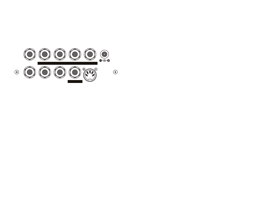
THE MF-104M BACK PANEL
This section provides greater detail of the connection points on the MF-
104M back panel.
AUDIO IN
FEEDBACK
TIME
LFO RATE
MIX
MIX OUT
DELAY OUT
FB INSERT
LFO AMT
MIDI IN
+9V
400 mA
AUDIO IN - This 1⁄4” jack provides high impedance, unbalanced audio in-
put. The Analog Delay accepts signals ranging from instrument to line level.
MIX OUT - This 1⁄4” jack provides an unbalanced audio output. When the
effect is on, this output carries the dry and wet signal blend set on the
front panel
MIX control. The level is determined by the DRIVE and OUTPUT
level controls. When the effect is off, the input signal passes only through
a high-quality buffer on its way to the output.
DELAY OUT - This 1⁄4” jack provides an unbalanced audio output. This is a
wet-only output, in phase with the
MIX output. The level is affected by the
OUTPUT LEVEL knob but not the MIX knob. This output can be used as a
second output in
STEREO applications or as a feed for phasing effects.
FEEDBACK (FB) INSERT - This 1⁄4” TRS jack is designed to be used with a
standard insert cable to process the BBD feedback signal path separately
from the dry signal path. This is an unbalanced, line level output and input.
The BBD output signal appears at the tip of the jack, and the return to the
device is applied to the ring of the jack.
Because these are line level signals, some means of attenuation or ampli-
fication may be required if using devices designed for lower signal levels,
such as typical guitar stomp boxes.
Note: Unlike the classic MF-104SD and MF-104Z, the FEEDBACK insert is placed
before the first delay in the feedback.