Moog Music Minimoog Voyager XL User Manual
Page 29
Page 30
Voyager XL User’s Manual - The Components
Page 31
Voyager XL User’s Manual - The Components
G – Primary LFO/Sample and Hold Section
The Primary LFO provides both Low Frequency Oscillator and Sample & Hold (S+H) modulation sources
for the Voyager XL Modulation Busses. The LFO provides triangle and square waves, while the S+H
produces a random voltage output. The LFO Frequency and S+H Rate are both controlled by the LFO
RATE knob, which is adjustable from 0.2 to 50 Hz. The LFO and S+H outputs are selectable as separate
modulation sources in both Modulation Busses.
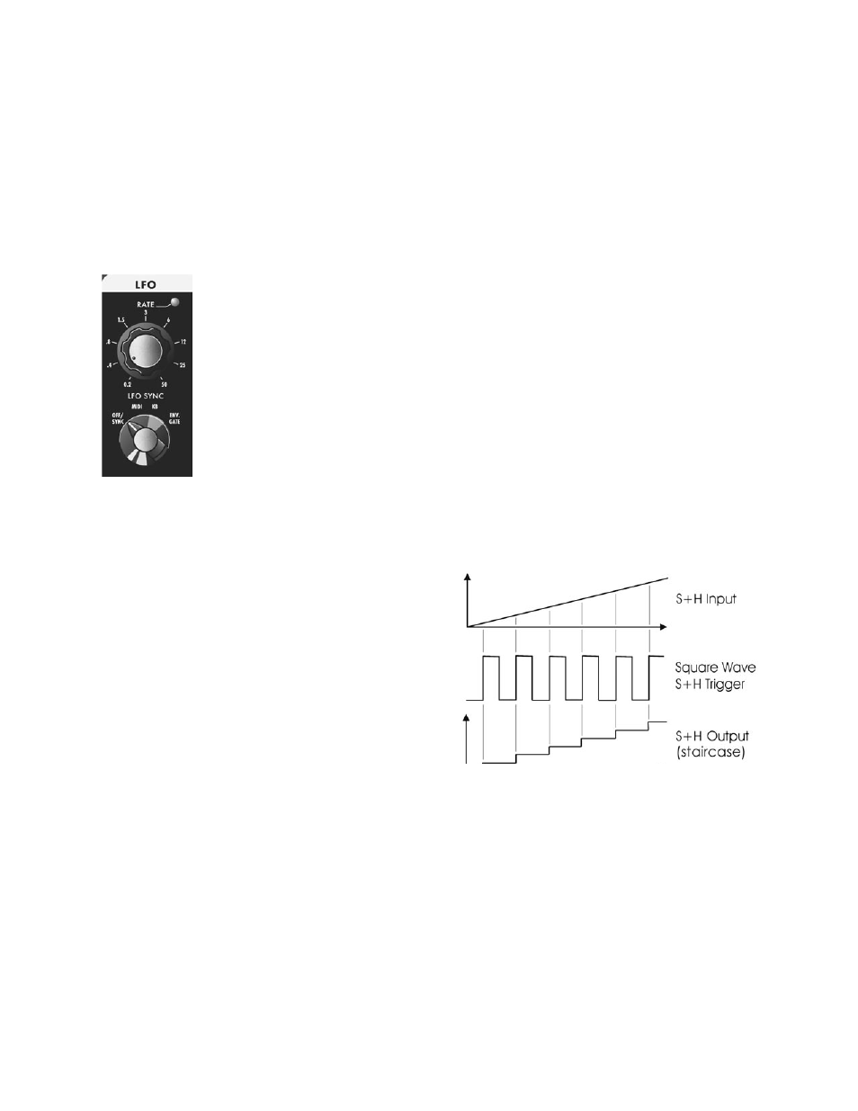
To generate the S+H function, the LFO’s square wave is used as the S+H Trigger,
while the Voyager XL Noise source is used for the S+H Input signal. For each
positive-going cycle of the LFO square wave, the voltage at the input of the S+H
circuit is sampled and held until the next cycle. Since the sample source is Noise (a
random signal), the voltage that appears at the output of the S+H circuit is a random
voltage that changes in time with the LFO.
The Voyager XL Sample and Hold circuit
can create more than just random signals –
interesting stepped modulation patterns
are also possible.
Inputs on the Modular Patch Panel allow additional flexibility with the Sample and
Hold circuit. For example, if a plug is inserted into the S+H Gate input, it will
disconnect the LFO trigger; an external gate signal can then be used to trigger the
S+H circuit. Similarly, a plug inserted into the S+H Input jack disconnects the Noise
source from the S+H input. In this circumstance when the S+H circuit is triggered,
the voltage at the tip of the plug is held at the output of the S+H circuit. This makes
it possible to get “staircase” modulation patterns as shown below.