Grain Systems PNEG-1711 User Manual
Page 10
PNEG - 1711
Page 10 of 22
06/30/2009
Digital Thermostat Owner’s Manual
1. Contents
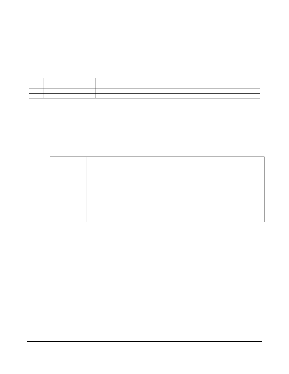
1.1 Digital Thermostat Contents
Qty
GSI Part Number
Description
1
D03-0852
Digital Moisture Control Thermostat
4
S-8570
2.5” #10-24 Machine Screw, Pan Head Phillip Stainless Steel
4
S-2010
Nut, Nylock #10-24 Zinc
2. Installation
2.1 Mounting in Control Panel
1. Turn the Main Power Disconnect to the “OFF” position.
2. Use the following table to document the wiring of the Honeywell that is being replaced, as this will be
referenced later in the manual.
# on Honeywell
Wire Description
(RTD) 1
(RTD) 2
(NO) 4
(SRC) 5
(110 VAC) 8
(NEUTRAL) 9
3. Remove the Honeywell controller from the control panel door. Loosen the flat head screw at the bottom of the
face of the dial. Grab the edges of the controller on the front of the control panel door and pull away from the
control panel. The controller should slide out, leaving a shell in the 1/4 din cut-out.
On the left and the right side of the shell, there is a flat head screw. Loosen these screws until you are able to
remove the shell from the control panel door.
4. Holes need to be drilled in the control panel door for mounting new thermostat. This is a two person job, as the
door needs to be open at least 90 degrees from closed when the drill breaks through to avoid damaging
internal circuitry. Refer to Figure 1 for drilling dimensions. Make sure all wires and human limbs are out of the
way when drilling. Section 6 is a drawing to scale that can be removed from this manual to be used as a guide
for drilling the holes.