Electrical power supply – Grain Systems PNEG-897 User Manual
Page 8
1999 Top Dry Wiring Diagrams
1999 Top Dry Wiring Diagrams
1999 Top Dry Wiring Diagrams
1999 Top Dry Wiring Diagrams
1999 Top Dry Wiring Diagrams
8
Power Supply
An adequate power supply and proper wiring are impor-
tant factors for maximum performance and long life of
the dryer. Electrical service must be adequate enough to
prevent low voltage damage to motors and control cir-
cuits (see Electrical Load Information).
It is necessary to know the distance from the unit to the
available transformer, and the horsepower of your fan
unit. Advise the service representative of your local power
supplier that an additional load will be placed on the line.
Each fan motor should be wired through a fused or cir-
cuit breaker disconnect switch. Check on KVA rating of
transformers, considering total horsepower load. The
power supply wiring, main switch equipment and trans-
formers must provide adequate motor starting and oper-
ating voltage. Voltage drop during motor starting should
not exceed 14% of normal voltage, and after motor is
running at full speed it should be within 8% of normal
voltage. Check Electrical Load Information for HP rat-
ings and maximum amp loads to properly size wire and
fusing elements. Standard electrical safety practices and
codes should be used. (Refer to National Electrical Code
Standard Handbook by National Fire Protection Asso-
ciation).
Transformer and Wiring Voltage Drop
Proper Installation of Ground Rod
It is very important that a Machine To Earth Ground
Rod be installed at the fan. This is true even if there is
a ground at the pole 15 feet away. Place the ground
rod that comes standard, within 8 feet of the dryer and
attach it to the dryer control panel with at least a #6
solid, bare, copper ground wire and the clamp pro-
vided. The grounding rod located at the power pole
will not provide adequate grounding for the dryer. The
proper grounding will provide additional safety in case
of any short and will ensure long life of all circuit boards,
Machine to Earth Grounding
It is not recommended that the rod be driven into dry
ground.
Follow these instructions for proper installation:
1.
Dig a hole large enough to hold 1 to 2 gallons
of
water.
2. Fill hole with water.
3. Insert rod through water and jab it into the ground.
4. Continue jabbing the rod up and down. The wa
ter will work its way down the hole, making
it possible to work the rod completely into
the ground. This method of installing the
rod gives a good conductive bond with the sur
rounding soil.
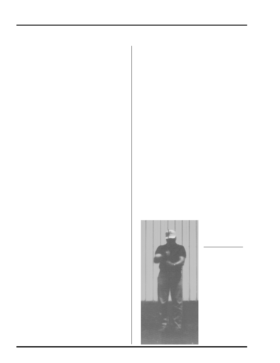
5. Connect the bare, copper ground wire to
the
rod with the proper ground rod
clamp. See
Figure 8.
6. Connect the bare copper ground wire to the fan
control boxes with a grounding lug.
Dig a hole large
enough to hold 1
or 2 gallons of
water. Work the
ground rod into
the earth until it
is completely in
the ground.
ELECTRICAL POWER SUPPLY
ELECTRICAL POWER SUPPLY
ELECTRICAL POWER SUPPLY
ELECTRICAL POWER SUPPLY
ELECTRICAL POWER SUPPLY
and the ignition system. The ground rod must be in
accordance with local requirements.
7. Ground wire must
not have any breaks
or splices.