Grain Systems PNEG-1472 User Manual
Page 16
16
PNEG-1472 L & B Series Field Installation
4. Installation Instructions
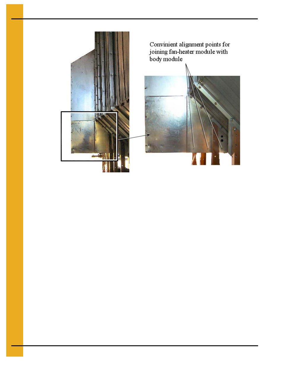
Figure 4D Alignment of Fan-Heater Module to Body Module.
4. Fan-Heater Enclosure Assembly (6034L, 7534L, 1038L, C2160B, C2175B,
C21100B)
The 6034L (C2160B), 7534L (C2175B), and 1038L (C21100B) model fan-heater enclosures are shipped
unassembled to the module in order to maintain an 8 ft shipping width. Field assemble following these
steps and refer to Figures 4E, 4F, 4G, and 4H.
1. Remove the louver assemblies from their shipping placement on the fan-heater module and discard
the shipping brackets.
2. Locate (6) floor frame extension channels (item #1 401-3914-9) and insert them inside the fan
module frame channels (see Figures 4E). Note that the fan-heater floor hardware will need to
be removed then reinstalled after channels are in place. Attach using the self tapping 5/16”
hardware (S-7221).
3. Locate items #4 (401-3910-7) and #5 (401-3911-5) reclaimer floor panels and position in place over
the floor frame extension channels. Attach using self tapping 5/16” hardware (S-7221).
4. Install items #9 (401-3910-9), #10 (401-3908-1), and #11 (401-3997-4) as shown. From this step
on it is highly recommended that the hardware be installed only loosley, allowing the wall
sheets to move slightly for aligning parts.
5. Install items #26 (401-3944-6) and #17 (401-3943-8) reclaimer end panels as shown in Figure 4E.
6. Install items #8 (401-3915-6), #2 (401-3941-2), and #3 (401-3942-0) fan reclaimer side panels
shown in Figure 4E. Note that the side panels should slip under the roof panels on the fan-