Banks Power Ford Trucks: (Diesel ’83 - 93 6.9 & 7.3L) Forced Induction- Sidewinder turbo system (Van) 6.9 & 7.3L User Manual
Page 9
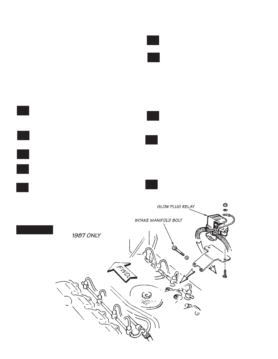
B. Remove the two intake manifold bolts located
between the third and fourth fuel injector (counting
from the front to the rear) on the right (passenger)
side of the engine. see
figure 9
.
C. Mount the glow plug relay to the glow plug relay
bracket (provided) using two
1
⁄
4
”-20 x 1” hex
bolts, two
1
⁄
2
” O.d. x
1
⁄
4
” I.d. washers, and two
1
⁄
4
”-20 nylock nuts. clamp the relay ground wire
under one of the nuts. See
figure 9
.
D. Install the bracket and relay on the
intake manifold using the intake bolts
a n d w a s h e r s r e m o v e d i n s e c t i o n b .
Route the wiring as shown in
figure 10
.
plastic clips may be removed from wire loom
jacket as required for rerouting wiring.
Remove pipe plug for oil feed connection,
located on lower left side at rear of block,
above and to the rear of the oil filter. See
figure
11
.
Install
1
⁄
8
” npt x -4an turbo oil feed elbow
in block. aim elbow at approximately one
o‘clock position. See
figure 11
.
Install oil feed hoses onto oil feed line tee.
use teflon tape on threads. See
figure 12
.
Install oil pressure sender onto oil feed line
tee. use teflon tape on threads. See
figure
12
.
Install oil feedline tee on intake manifold,
using rear-most intake manifold mounting
bolt hole, on the left side. use original bolt and
washer. Replace the other left rear manifold bolt
with one new
3
⁄
8
”-16 x 2
1
⁄
2
” hex head bolt and
original washer.
nOte: Oil feed line to block must go under injector
tubing loop at rear-most injector.
connect oil feed hose to elbow installed in
step 21.
Lengthen the oil pressure gauge sender
wire as follows:
cut the plug from the wire loom leaving 2-3
inches of wire attached to the plug. Lengthen the
wire from the loom as required using wire and
connector provided in the kit. Route the wire in
front of the intake manifold air inlet opening to
the gauge sender. Keep wire clear of any moving
parts. note: connectors squeeze together onto
the wire with pliers. Re-install plug on sender.
tie wrap glow plug wiring and throttle cable
at rear of intake manifold (snugly but not
tight enough to cause binding or kinking). see
figure 13
.
cut one 6 x 14” heat blanket into one piece
6 x 6” and one piece 8 x 6”. Wrap one 8 x
6” piece around the glow plug wiring and throttle
cable near turbine housing. secure using wire ties
provided (See
figure 14
). Save the other pieces
for later installation (to be used around hoses for
rear heater and/or air conditioning where close to
exhaust).
cut ear off of right side of transmission bell
housing, using a hacksaw. see
figure 15
.
27.
26.
25.
24.
23.
22.
21.
20.
FIguRE 9
9
29.
28.
P.N. 96308 V.2.0