General installation – Banks Power Ford Trucks: (Diesel ’83 - 93 6.9 & 7.3L) Forced Induction- Sidewinder turbo system (Van) 6.9 & 7.3L User Manual
Page 6
6
gENERAL INStALLAtION
Remove engine cover. disconnect ground
cables from both batteries. Disconnect
electrical connections from top of injection pump.
Disconnect plastic air inlet duct. Remove air
cleaner housing and element. Leave plastic
air inlet duct in place for engine compartment
cooling.
Disconnect wire from oil pressure sender
unit, located on rear of engine.
Remove oil pressure sender unit and fitting
from rear of engine. Retain sender for later
installation.
Install
1
⁄
8
” npt brass pipe plug in hole at rear
of block where oil pressure sender unit and
fitting were removed. use teflon tape on threads.
On Automatic Transmission Vehicles
Only, remove steel tube connected to
transmission modulator valve.
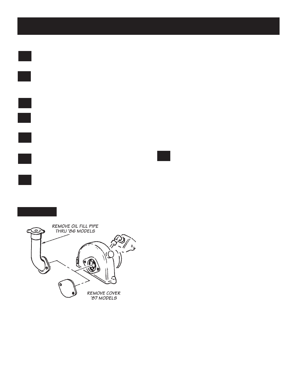
Remove oil fill-pipe from front of engine.
(Note: 1987 models use an inspection cover
plate, remove cover plate). see
figure 4
.
INJECTION PUMP ADJUSTMENT
to obtain the maximum available performance
from your sidewinder turbo system, it is necessary
to make an adjustment to the fuel injection pump.
the pump adjustment increases the fuel delivery
capacity of the pump. this adjustment is made by
turning an internal screw, found within the pump.
the pump is infinitely adjustable from the standard
setting to an approximately 50% increase in
power. BanKs recommends one of two settings,
as follows:
LEVEL 1: Exceeds 30 percent increase in rear
wheel horsepower. suitable for general use, work
trucks and towing. Recommended for heavy loads
and most applications. (this is the ONLy emissions
legal setting.)
LEVEL 2: approximately 50 percent increase in
rear wheel horsepower. for high performance
use. (this setting is nOt emissions legal.)
nOte: exhaust gas temperature (egt) must not
exceed 1150°f, as shown on the egt gauge
(pyrometer) furnished with the kit. If the egt
approaches this temperature under heavy, uphill
load, the fuel pump capacity adjustment must
be reduced. the level one pump setting will
cause no problem, very rarely approaching this
temperature.
adjust injector pump delivery for desired
application, as follows:
nOte: the engine must be cOLd before starting
this procedure.
NOtE: utmost cleanliness should be exercised.
DO NOt allow any foreign material, including lint
from rags, to enter the injector pump during the
adjustment procedure — the lint from a rag can
clog an injector. Lay any removed parts on a clean
newspaper during the adjustment procedure.
A. place a drip pan under the rear of the engine,
under the flywheel inspection cover area, to catch
spilled fuel. clean the area of the pump in the
vicinity of the small access cover, located on the
left side of the pump, as viewed from the front of
the vehicle, with diesel fuel or parts solvent. dO
nOt clean the pump while it is hot; doing so
may damage the pump.
B. Remove the cover plate, retained by two small
screws. use care not to damage the rubber
gasket; it will be reused during reassembly.
IMPORTANT: utmost care must be used to
prevent foreign objects and dirt from falling into
the pump to prevent damage.
C. Rotate engine by hand, in a clockwise direction,
using a breaker bar, short extension and suitable
socket on the harmonic balancer retaining bolt.
align the injector drive pin, as viewed through the
opening for the oil fill pipe, in a straight up (12
o‘clock) position. using a small mirror, check that
the allen head adjustment screw is visible within
the inspection hole. It may be necessary to rotate
the engine somewhat more to gain access to the
adjusting screw. see
figures 5 and 6
. Do Not
attempt to Rotate the engine With the
8.
7.
6.
5.
4.
3.
2.
1.
FIguRE 4
P.N. 96308 V.2.0