Banks Power Ford Trucks: (Diesel ’83 - 93 6.9 & 7.3L) Forced Induction- Sidewinder turbo system (Van) 6.9 & 7.3L User Manual
Page 7
7
Starter.
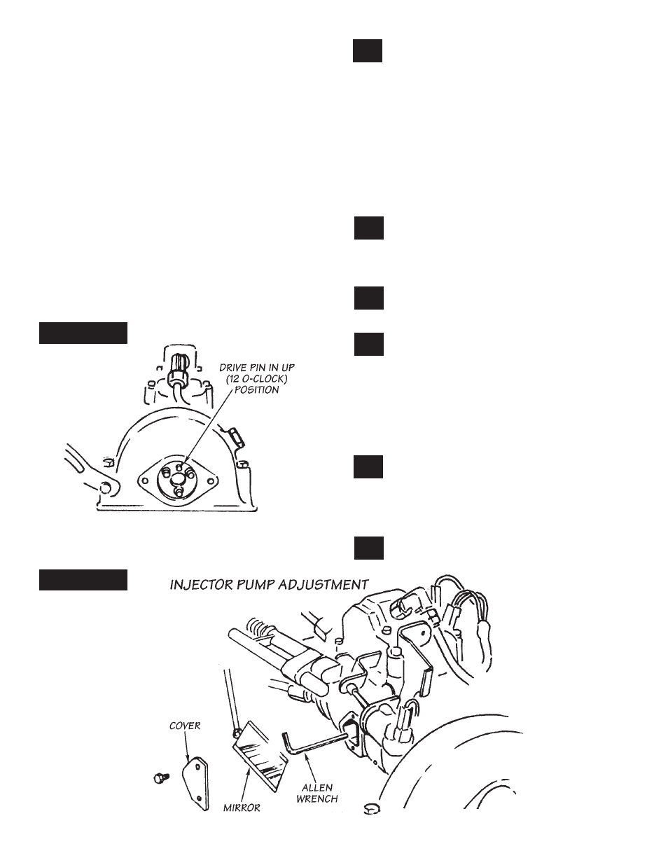
D. using a
5
⁄
32
” allen wrench (with sharp corners),
rotate the screw to obtain the desired
performance level:
LEVEL 1:
1
⁄
4
turn, clockwise
LEVEL 2:
3
⁄
8
turn, clockwise
nOte: the allen screw turns fairly tightly and
is self locking. turning the screw clockwise
increases fuel delivery capacity. Keep track of
your adjustments.
E. Replace access cover on pump. again exercise
care to prevent foreign material from entering
pump.
F. Wipe up any spilled fuel remaining on valley
cover. this completes the pump adjustment
procedure.
Reroute the injector return hoses. Refer to
figure 7
, which shows how the return lines
should be routed. Remove and install necessary
components as required to complete the system
as shown. (Additional hose is provided for the
rerouting.) note that there should be a minimum
of four inches clearance between the injector
return line and the turbine housing or turbo
mounting bracket when turbo is installed.
On Automatic Transmission Vehicles Only, also
be sure that the new injector return hose does
not interfere with the transmission kickdown
linkage.
Remove the engine lifting lug from left rear
of the intake manifold. Replace bolts with
new
3
⁄
8
”-16 x 2
1
⁄
2
” hex head bolts provided, and
original washers. (do not use original bolts or
reinstall lifting lug.).
Remove the engine lifting lug from left rear
of the intake manifold. Retain the bolts for
later installation.
Remove the crankcase anti-depression valve
(the round sheet metal can be attached to
the rear of the intake manifold). Remove standpipe
and grommet from valley cover. (standpipe may
come out attached to anti-depression valve.) Retain
anti-depression valve and mounting bolts for later
installation. note, 1987 models: Remove short
length of hose and clamp from anti-depression
valve.
carefully clean around the hole where the
original grommet was installed at the rear
of the valley cover and where the anti-depression
valve was mounted on intake manifold. (use
acetone, lacquer thinner or other non-oil based
solvent.).
Install grommet in valley cover as follows.
fill grommet groove with Rtv silicone
12.
11.
10.
9.
FIguRE 6
FIguRE 5
13.
14.
P.N. 96308 V.2.0