Banks Power Universal Car & Truck: (Gas or Diesel ’50 - 14 Universal) Water-Methanol: Straight-Shot and Double Shot, Vehicle specific applications User Manual
Page 20
20
97651 v.1.0
4c.
If there is debris present in the con-
tainer after running the initial test, re-fill
the system tank with clean distilled water
and repeat “TEST” mode until all debris
remaining from installation has been
purged from the system. Check all tubing
connections for leaks.
: If the controller dis-
plays an error code, or the pump
does not turn on when activating
“TEST” mode, refer to the error code
index (page 27) and use system
schematic (P/N 97650-A or 97651-
A) to ensure all components were
connected to appropriate connec-
tors. Check all connectors for full
engagement. If pump turns on, but
water does not flow out of tubing,
use system schematic (P/N 97650-A
or 97651-A) to ensure system was
plumbed correctly.
4d.
Remove all injector nozzle(s) from
their mounting ports on the engine and re-
connect them to their supply tubes. Empty
water from the clear container used in
the previous step, insert the assembled
injector nozzles and supply lines back into
the container and re-secure in a stable
position.
4e.
Initiate another “TEST” mode from
the injection controller and examine the
spray pattern from each nozzle. A clean,
evenly-distributed spray cone should be
visible from every nozzle (some moderate
pulsation is normal and will vary based on
nozzle selection). Examine the threaded
joint between each nozzle and nozzle
holder carefully for any leaks during this
high pressure test - tighten the assembly
in quarter turn steps until corrected.
4e.
Dribbling or spitting from one or
more nozzles while other nozzles atomize
properly indicates a partially plugged nozzle
or filter - exit “TEST” mode, remove the
nozzle from the holder fitting. Use pliers to
unscrew screen holder and examine the
screen for debris.
4g
. If no leaks are noted
and each nozzle is atomizing correctly,
exit “TEST” mode and turn off the vehicle’s
ignition switch to power down the injec-
tion controller.
5.
Double-check tubing and all connec-
tions for leaks. Permanently install injec-
tion nozzles and tubing into appropriate
locations, and reconnect pump pressure
switch.
: To setup the Straight-
Shot injection controller for first-
time use, several selections needs
to be made for the controller to con-
figure it for your specific application.
6.
Turn vehicle ignition to on without
starting the vehicle. Select the “INPT”
(input) sub-menu using “MENU” button to
scroll through main menu and “SELECT”
button to select “INPT”. Scroll through the
“INPT” menu and select “MAP” (Manifold
Absolute Pressure) for boosted applica-
tions or “THRT” (throttle) for non-boosted
applications. “MAP” is the default input
method, and requires that a specific MAP
sensor type be selected (in the following
step). If “THRT” mode is selected, no fur-
ther input configuration is required - the
controller will display throttle value from
0-100% based on a 0.5V-4.5V range.
: Main menu, “OCTL”
submenu, and “DISP” sub-menu
will display different options based
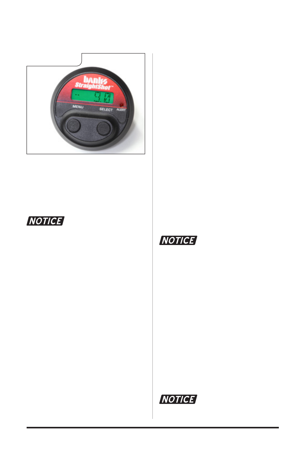
Figure 44