Banks Power GM Motorhomes: (Gas ’82 - 95 7.4L) PowerPack system (Carbureted, dual air pump) User Manual
Page 9
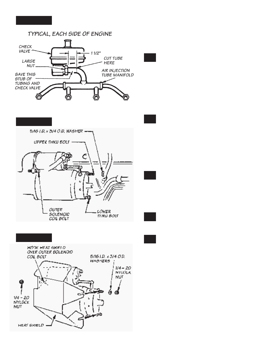
with a torch to loosen the joints. an alternative
method is to hacksaw through the individual air
tubes, as this portion of the air injection tubing
will not be reinstalled. save the two large black
check valve bodies and any portion of the chrome
air injection tube manifolds that was removed
with them.
Label the check valves right and left for
identification later. Measure and mark each
air injection tube assembly at a point 1
1
⁄
2
inches
from the outside edge of the large nut (see Figure
10
). Remove each check valve from the air injec-
tion tube assemblies, and saw through the tub-
ing at the locations marked. The large tube nuts
require a wrench with a 1
3
⁄
8
jaw opening. Remove
any burrs from the short stubs of tubing cut from
the tube assemblies. reinstall these tube stubs
in each of the check valves. save the check valve
mounting bolts.
Install the starter heat shield on the
starter motor as follows: loosen the
lower starter motor thru-bolt 3–4 turns. Make
sure the outer the outer solenoid coil bolt is snug.
Place a
5
⁄
16
” i.d. x
3
⁄
4
” O.d. flat washer over the stud
end of the upper starter motor thru-bolt. Hook the
starter heat shield onto the end of the outer sole-
noid bolt and slide the front of the shield onto the
two thru-bolts. The shield goes under the loos-
ened head of the lower bolt and over the washer
on the upper bolt. See Figure
11.
Tighten the lower starter motor thru bolt
against the heat shield. Place a
5
⁄
16
” i.d. x
3
⁄
4
” o.d. flat washer and a
1
⁄
4
–20 nylock nut on
the stud end of the upper thru bolt, and tighten.
install a
1
⁄
4
–20 nylock nut on the exposed end of
the outer solenoid coil bolt and tighten. Make sure
heat shield will not short against any wiring. See
Figure
12.
included in this PowerPack kit are two
inline check valves. Install these valves on
the
1
⁄
2
” pipe thread connection on the Banks tubu-
lar exhaust manifolds (see Figure
1
).
clean exhaust manifold flange surfaces on
cylinder heads of any loose rust and car-
bon. Working from under the vehicle, guide the
Banks exhaust manifolds up into place and bolt
them to the cylinder heads with the longer mani-
fold bolts provided.
NOTE: Bolt a check valve mounting bracket, pro-
vided, under the 3rd (right hand) and 6th (left
hand) exhaust manifold bolts, as shown in Figure
13.
Bolts are counted from front to rear on
engine.
NOTE: Some air conditioner compressor brackets
may have to be filed or ground slightly to clear the
top of the left hand manifold flange.
21.
22.
20.
19.
18.
9
P.n. 96341
fiGure 10
fiGure 11
fiGure 12