Figure 5 figure 6 – Banks Power GM Motorhomes: (Gas ’82 - 95 7.4L) PowerPack system (Carbureted, dual air pump) User Manual
Page 6
now bolt the bulkhead fitting to the
bracket using four no. 6 x
1
⁄
2
” sheet metal
screws. Hook up the factory flex hose from the
air filter base to the bulkhead fitting.
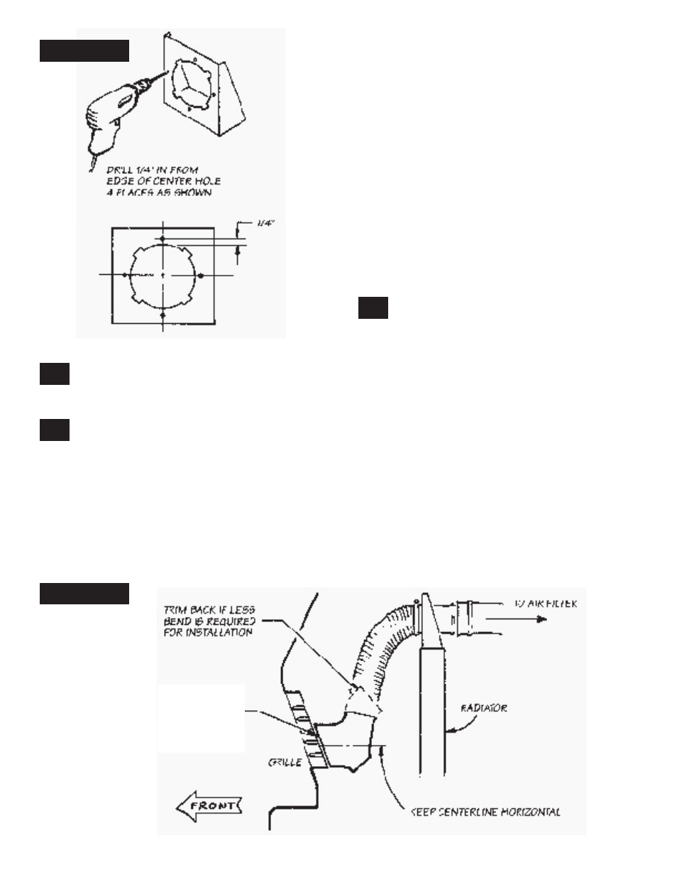
determine a location for the Banks super-
scoop™. It should be placed as low as pos-
sible directly behind the grille, with the air inlet
opening pointing straight ahead. If the grille is at
an angle, the super-scoop should be trimmed at
an angle to place the air inlet opening against the
back side of the grille with the centerline of the
inlet opening horizontal. See Figure
6
. use heavy
snips or a hack saw to trim the air inlet opening
of the super-scoop.
The height between the super-scoop and the air
inlet hood should be as great as possible to pre-
vent any rain water not eliminated by the scoop’s
water drain hole from climbing up into the air fil-
ter. The curved outlet section of the super-scoop
may be trimmed back if less bend is required
to make a more streamlined hose routing. See
Figure
6
.
for motorhomes that do not have the plastic air
inlet hood or any air inlet ducting connected to
the snorkel on the air filter base, we have provid-
ed an additional 3-foot length of a 4” diameter flex
hose to run from the air filter base past the radia-
tor. there must be at least a 2
1
⁄
4
” high clearance
between the floor of the coach and the top of the
radiator bulkhead panel for the flex hose to pass
through. If this clearance does not exist, it may be
possible to mount the super-scoop somewhere
else, such as in a wheelwell, etc. It should be
located where it will receive the coolest air avail-
able, and be shielded from foreign materials such
as flying stones and excess water spray.
once a location has been determined for
the Banks super-scoop, mount it using one
of the following methods.
The super-scoop may be mounted by several
means. If the grille consists of horizontal bars or a
perforated metal screen heavy enough to support
the inductor, it may be secured using four 14”
clear nylon cable ties, provided, slipped through
the ears on the super-scoop and through the
grille. See Figure
7.
an alternate method is to mount the scoop using
the four perforated metal straps provided. These
can be bent as required and attached to the
scoop’s ears with the
1
⁄
4
–20 x 1
1
⁄
4
hex bolts,
1
⁄
4
–20
nylock nuts and
3
⁄
4
o.d. x
5
⁄
16
I.d. flat washers pro-
vided. The opposite end of the straps may be
attached to any convenient mounting points such
as the gravel pan, grille brackets, etc. as required,
with four no. 10 x
3
⁄
4
” sheet metal screws pro-
vided. a combination of cable ties and straps may
also be used.
6
P.n. 96341
10.
8.
9.
triM front of suPer-scooP
to Match anGle of Grille
fiGure 5
fiGure 6