Figure 16 figure 15 – Banks Power GM Motorhomes: (Gas ’82 - 95 7.4L) PowerPack system (Carbureted, dual air pump) User Manual
Page 11
Open a number 56 hose clamp and thread it
through to slots on the oil filter heat shield.
See Figure
14
. Position the heat shield on the oil
filter to provide protection from the closest mani-
fold pipe, then tighten clamp.
Install an exhaust “doughnut” seal in the
right exhaust manifold outlet flange. Lightly
tap the seal into place with a hammer until it
seats.
install three
3
⁄
8
” x 2
1
⁄
4
” studs in the right
exhaust manifold outlet flange. Two
3
⁄
8
coarse thread nuts jammed against each other on
the outer stud threads may be used to wrench the
studs into place. use anti-sieze compound on the
threads.
install three
3
⁄
8
” x 2
7
⁄
8
” studs in the left
exhaust manifold outlet flange. use anti-
sieze compound on the threads.
Remove the old “doughnut” seal from the
heat riser valve (ePR) if still attached, and
replace with new seal provided. Lightly tap the
seal into place to seat it.
slide the heat riser valve into position on
the studs of the left exhaust manifold out-
let. note that the actuating diaphragm faces up
and to the left.
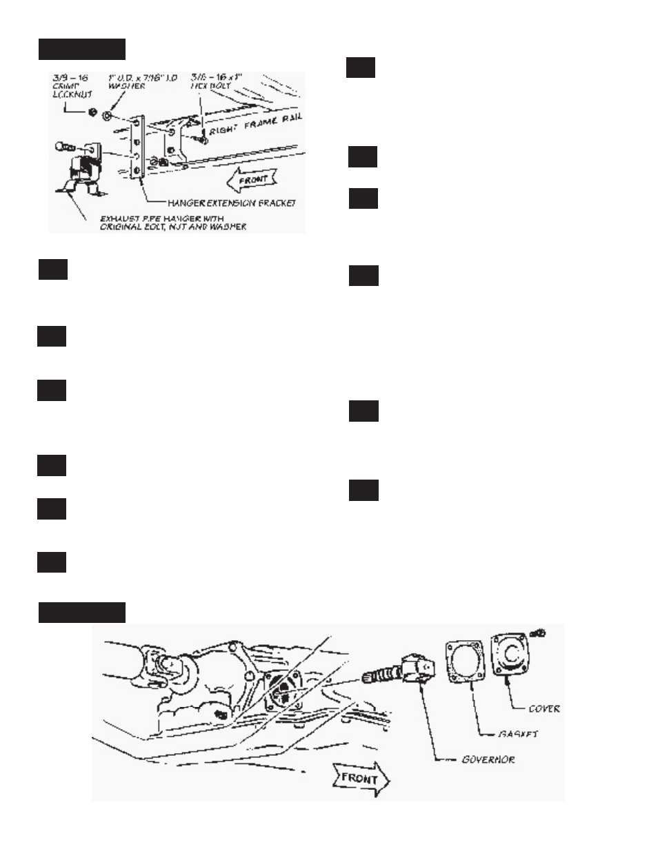
Remove the forwardmost exhaust pipe
hanger from the right hand frame rail. Install
the hanger extension bracket, provided, on the
frame rail at this location. use two
3
⁄
8
–16 x 1” hex
bolts, two 1” O.d. x
7
⁄
16
” i.d. flat washers and two
3
⁄
8
–16 crimp locknuts to secure the extension. See
Figure
15.
Reinstall the exhaust pipe hanger to the
extension bracket using the original bolt,
nut, and washer.
Install the Banks exhaust head pipes and
muffler using the original nuts, wash-
ers, springs, etc. use anti-sieze on the threads.
Position the pipes such that they can mount in the
two forwardmost exhaust pipe hangers. Tighten
all nuts, clamps, etc. See Figure
1.
Working from the muffler back, install the
tail pipe sections most appropriate for your
vehicle. Because of various chassis lengths and
configurations, your tail pipe hangers may or may
not line up properly for the tail pipe routing. We
have provided three universal tail pipe hangers
that may be attached to crossmembers, frame
rails, etc. with the remaining
3
⁄
8
– 16 x 1” hex
bolts, nuts, and washers. see figure 1 for tail pipe
assembly. Maintain 1
1
⁄
2
” of clearance to frame and
body to prevent rattles and hot spots.
Install the chrome tail pipe extension tip
and chrome tailpipe heat shield per Figure
1.
extension tip may be slid in or out over tail
pipe until desired length is obtained for body
width. Then clamp extension to tail pipe using 3”
u-clamp.
Install new vacuum hose, provided, from
connection on heat riser (ePR) valve to
metal vacuum line. Keep this hose as far as pos-
sible from exhaust system heat. Plastic cable ties
are provided to attach the hose to crossmembers,
etc. The metal vacuum line may be bent slightly to
aim it toward the ePR valve.
32.
33.
34.
35.
36.
37.
11
P.n. 96341
29.
30.
31.
fiGure 16
fiGure 15
28.
26.
27.