Velleman DVR4H3 Quick Installation Guide User Manual
Page 5
DVR4H3
Rev. 01
18/01/2012
©
Velleman nv
5
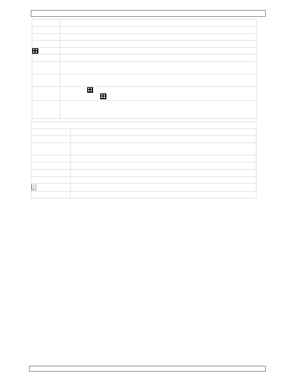
PLAY
Press to play the recorded video.
SLOW
In playback mode, press to play the recorded file slowly.
ZOOM
In live or playback mode, press to enlarge the image of the selected channel.
SEQ
Press to show all screens sequentially in full screen mode. Press again to quit.
4CH: Press to show the 4 channel display mode.
1 ~4
Press a button to select the corresponding channel.
SEARCH
Enter time search mode. Set time range and press START to see all recordings within
the time range.
AUDIO
= SLOW + ZOOM
Press SLOW and ZOOM simultaneous to select live or play-back sounds.
P.T.Z.
= SLOW +
Press SLOW and
simultaneous to enter or exit PTZ control mode.
USB port
(2x)
Connect a USB flash drive for video backup to one USB port; connect a USB mouse
to the other.
Note: do not connect two USB flash drives or USB mice at the same time.
rear panel
LAN port
Connect the DVR to a local network by plugging a network cable into this port.
VGA
connector for video monitor*
AUDIO IN
4 audio input channels to connect four external audio sources e.g. from cameras
with audio.
AUDIO OUT
1 audio output to connect to an audio device, e.g. a speaker (mono).
VIDEO IN
4 video input channels to connect 4 external video sources e.g. cameras.
MONITOR
1 video output channel to connect the DVR to the main monitor.
EXTERNAL I/O
use a 9 pin DSUB connector to connect external signals e.g. alarm, PTZ, ...
power switch
19V DC
Power supply input.
6.
Hardware setup
Installing the Hard Disk Drive (HDD)
Refer to the illustrations on page 2 of this manual.
•
Obtain a suitable HDD (not included), type SATA (Serial Advanced Technology Attachment). The
HDD must be formatted.
•
Make sure to unplug the device from the mains before servicing and do not touch any electronic
circuitry to avoid electrostatic discharge.
•
Unscrew the 6 screws (1 on either side and 4 on the back) that hold the cover in place.
•
Lift the cover (back first).
•
Screw the mounting brackets on the HDD (screws included).
Note: the PCB must be facing upwards when mounting the HDD into the DVR.
•
Connect the SATA data cable and power supply to the HDD.
•
Screw the HDD on the bottom of the DVR housing PCB facing upwards using the included screws.
•
Close the cover (front first) and secure it with the 6 screws.
Connecting a video monitor
•
Obtain a suitable monitor (not included) and connect it to the BNC or VGA video output port on the
back of the DVR.
Connecting the power supply
•
Plug the DC output connector of the included power adaptor into the 19VDC power input at the
back of the DVR.
WARNING: only use the included adaptor.
•
Plug the included power cable into the adaptor input connector and plug the other end into the
mains. Do not switch the DVR on yet.
Connecting a camera
•
Obtain up to four suitable cameras (not included). Each camera needs its own power supply.