Velleman CV045 User Manual
Page 4
CV045
V. 01 – 25/05/2012
4
©Velleman nv
•
package contains:
o
4-channel balun receiver with power supply built-in: 1 piece
o
passive video and power baluns: 4 pieces
o
mounting bracket for rack mounting: 2 pieces
o
coax cable for connection to monitor/DVR: 4 pieces.
5.
Overview
Refer to the illustrations on page 2 of this manual.
Receiver Balun
1 on/off switch
5
video connector for camera (BNC)
2 video output to DVR or monitor (BNC)
6
UTP cable connector
3 video inputs from camera (UTP cable)
7
power connector for camera
4 power supply connector
Connection scheme
A CCTV camera (not included)
D
DVR / monitor (not included)
B balun
E
CV045 receiver
C UTP cable (CAT5E/6, not included)
6.
Hardware installation
Refer to the illustrations on page 2 of this manual.
You can connect up to 4 cameras to the receiver.
1. Connect the balun’s video connector [5] to the video connector of the camera [A].
2. Connect the balun’s power connector [7] to the power connector of the camera [A].
3. Connect the baluns [B] to the receiver [E] using CAT5E/6 cables [C].
Note: you can use either T568A or T568B cables (see wiring scheme further in this manual). Make
sure that both ends use the same wiring.
Note: the maximum cable length is 250m. For voltage drops over long distances, refer to the table
further in this manual.
4. Connect the receiver’s video output [2] of each camera to a monitor or DVR [D] using coax cables.
Use one cable per connected camera.
5. Plug the receiver’s power cord into the power supply connector [4].
6. Plug the power cord into a suitable mains socket (see Technical Specifications).
7. Switch on the receiver using the on/off switch [1].
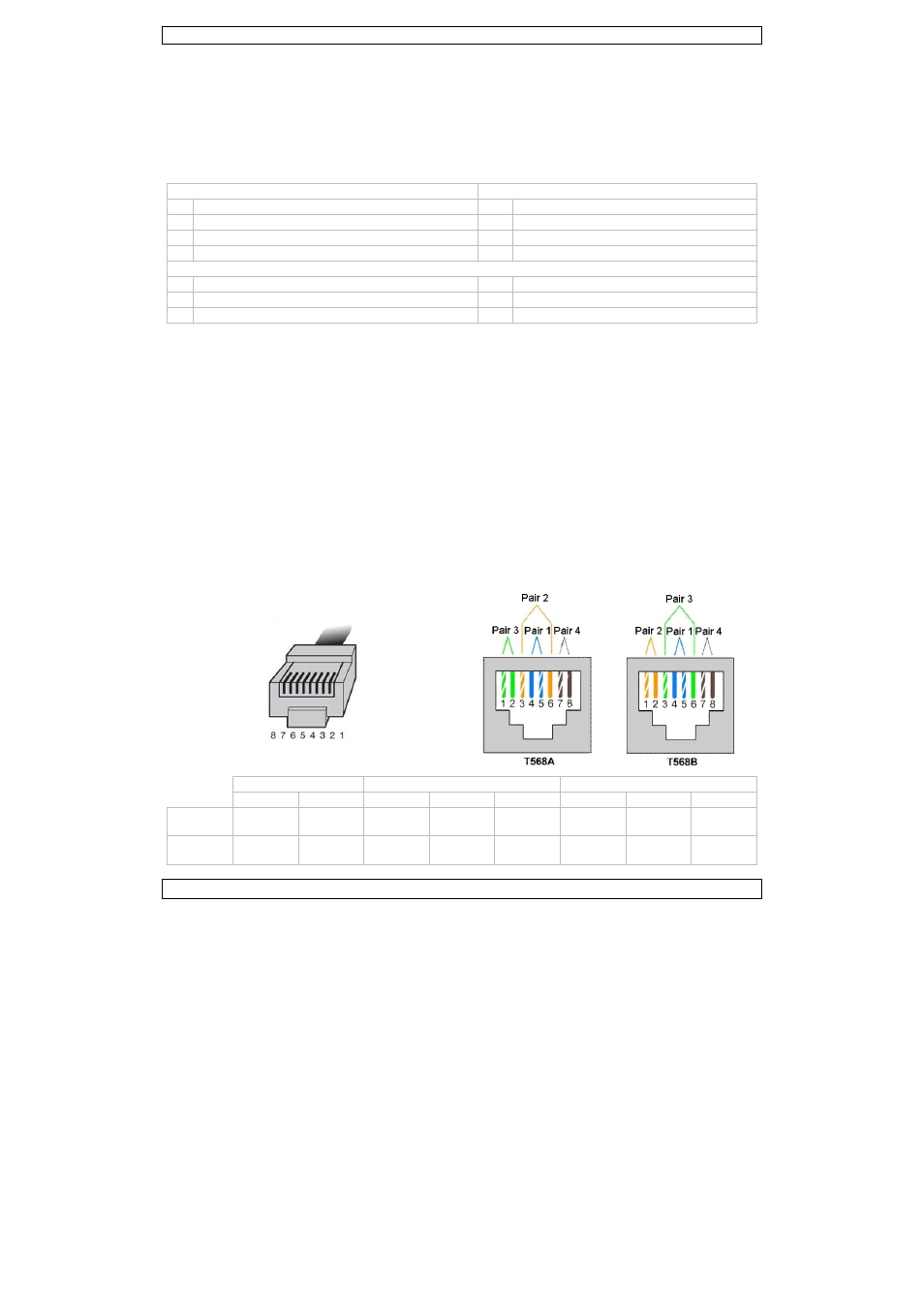
Wiring scheme
Video
Power –
Power +
1 2 3 4 5 6 7 8
T568A
white
green
green
white
orange
blue white
blue
orange white
brown
brown
T568B
white
orange
orange
white
green
blue white
blue green white
brown
brown