Velleman HAA263D User Manual
Page 3
HAA263D
02 (15/11/2013)
VELLEMAN
3
5.
Installation
•
This keypad should be installed and serviced by a qualified person only.
•
Choose an easily accessible location where the keypad is protected from harsh environmental
conditions such as rain and bright sunlight, and away from heat producing devices.
•
Have a qualified person installing the electrical leads (4) that are necessary for the connection of
the keypad to the master control unit.
•
Remove the keypad from the mounting frame by removing the screw at the bottom and pulling
gently forward.
•
Mount the mounting frame over the leads coming from the master control unit. Do not damage
the leads when doing this.
•
Remove the back cover of the keypad by removing the screws at the four corners.
•
Make sure there is no power on the leads. Connect the leads to the connector block in the keypad
as indicated on the PCB.
•
It is also possible to install a tamper switch (not included).
•
Re-mount the back cover with the 4 screws.
•
Place the keypad back in the mounting frame. Make sure the cabling is not damaged in the
process. Remount the screw at the bottom.
•
Apply power to the leads (via the master control unit).
•
There are no user-serviceable parts. Contact your dealer for spare parts if necessary.
6.
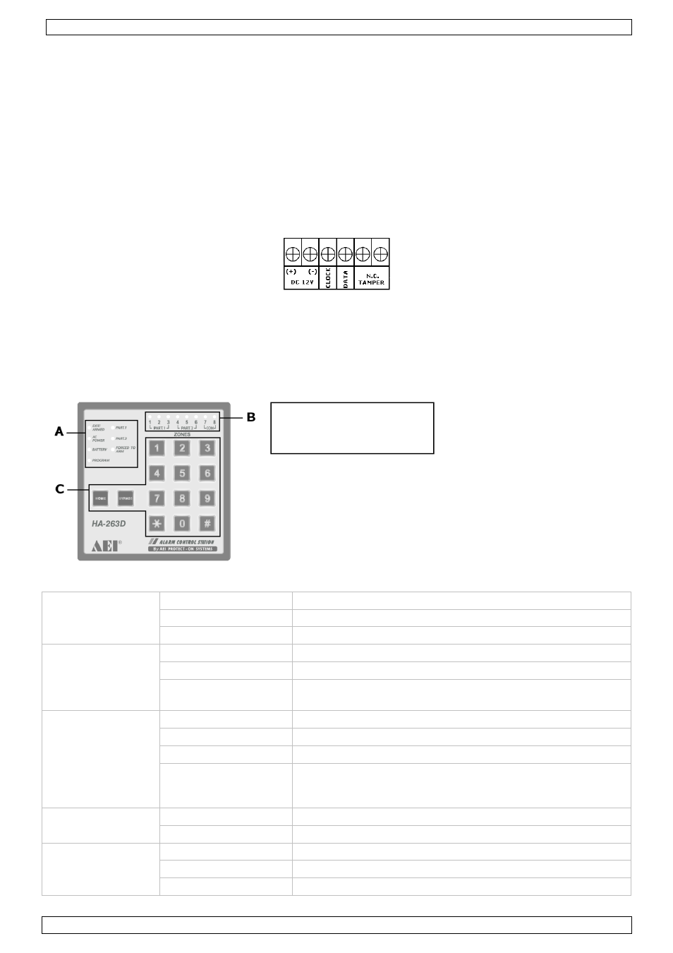
Keypad description
A.
General status LEDs
EXIT/ARMED
ON
System armed (whole system or one of the partitions)
OFF
System disarmed (the whole system)
Flash
System in exit delay period
AC POWER
ON
AC power normal
Flash
AC power failure
Flash Alternatively
with Battery LED
System in Standby mode
BATTERY
ON
Battery low
OFF
Battery normal
Flash
Battery under testing
Flash Alternatively
with AC power
LED
System in Standby mode
PROGRAM
ON
System in programming mode
OFF
System in normal operation mode
PART. 1
ON
Partition 1 armed
OFF
Partition 1 disarmed
Flash
During Exit Delay
A. General status LEDs
B. Zone status LEDs
C. Control key buttons