Appendix a - technical specifications, Page 24 – Velleman DCA55 User Manual
Page 24
Atlas DCA User Guide
October 2007 – Rev 7
Page 24
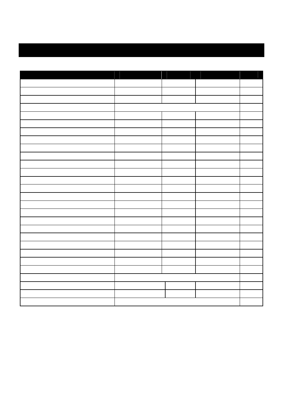
Appendix A - Technical Specifications
All values are at 25°C unless otherwise specified.
Parameter
Min
Typ
Max
Note
Peak test current into S/C
-5.5mA
5.5mA
1
Peak test voltage across O/C
-5.1V
5.1V
1
Transistor gain range (H
FE
)
4
65000
2
Transistor gain accuracy
±3% ±5 H
FE
2,8
Transistor V
CEO
test voltage
2.0V
3.0V
2
Transistor V
BE
accuracy
-2%-20mV
+2%+20mV
8
V
BE
for Darlington
0.95V
1.00V
1.80V
3
V
BE
for Darlington (shunted)
0.75V
0.80V
1.80V
4
Acceptable transistor V
BE
1.80V
Base-emitter shunt threshold
50kΩ
60kΩ
70kΩ
BJT collector test current
2.45mA
2.50mA
2.55mA
BJT acceptable leakage
0.7mA
6
MOSFET gate threshold range
0.1V
5.0V
5
MOSFET threshold accuracy
-2%-20mV
+2%+20mV
5
MOSFET drain test current
2.45mA
2.50mA
2.55mA
MOSFET gate resistance
8kΩ
Depletion drain test current
0.5mA
5.5mA
JFET drain-source test current
0.5mA
5.5mA
SCR/Triac gate test current
4.5mA
7
SCR/Triac load test current
5.0mA
Diode test current
5.0mA
Diode voltage accuracy
-2%-20mV
+2%+20mV
V
F
for LED identification
1.50V
4.00V
Short circuit threshold
10Ω
Battery type
MN21 / L1028 / GP23A 12V Alkaline
Battery voltage range
7.50V
12V
Battery warning threshold
8.25V
Dimensions (body)
103 x 70 x 20 mm
1.
Between any pair of test clips.
2.
Collector current of 2.50mA. Gain accuracy valid for gains less than 2000.
3.
Resistance across reverse biased base-emitter > 60kΩ.
4.
Resistance across reverse biased base-emitter < 60kΩ.
5.
Drain-source current of 2.50mA.
6.
Collector-emitter voltage of 5.0V.
7.
Thyristor quadrant I, Triac quadrants I and III.
8.
BJT with no shunt resistors.
Please note, specifications subject to change.