Vishay high power products, Phase control thyristors (stud version), 180 a, Ordering information table – C&H Technology 181RKI...PbF Series User Manual
Page 7
www.vishay.com
For technical questions, contact: [email protected]
Document Number: 94382
6
Revision: 30-Apr-08
180RKI...PbF /181RKI...PbF Series
Vishay High Power Products
Phase Control Thyristors
(Stud Version), 180 A
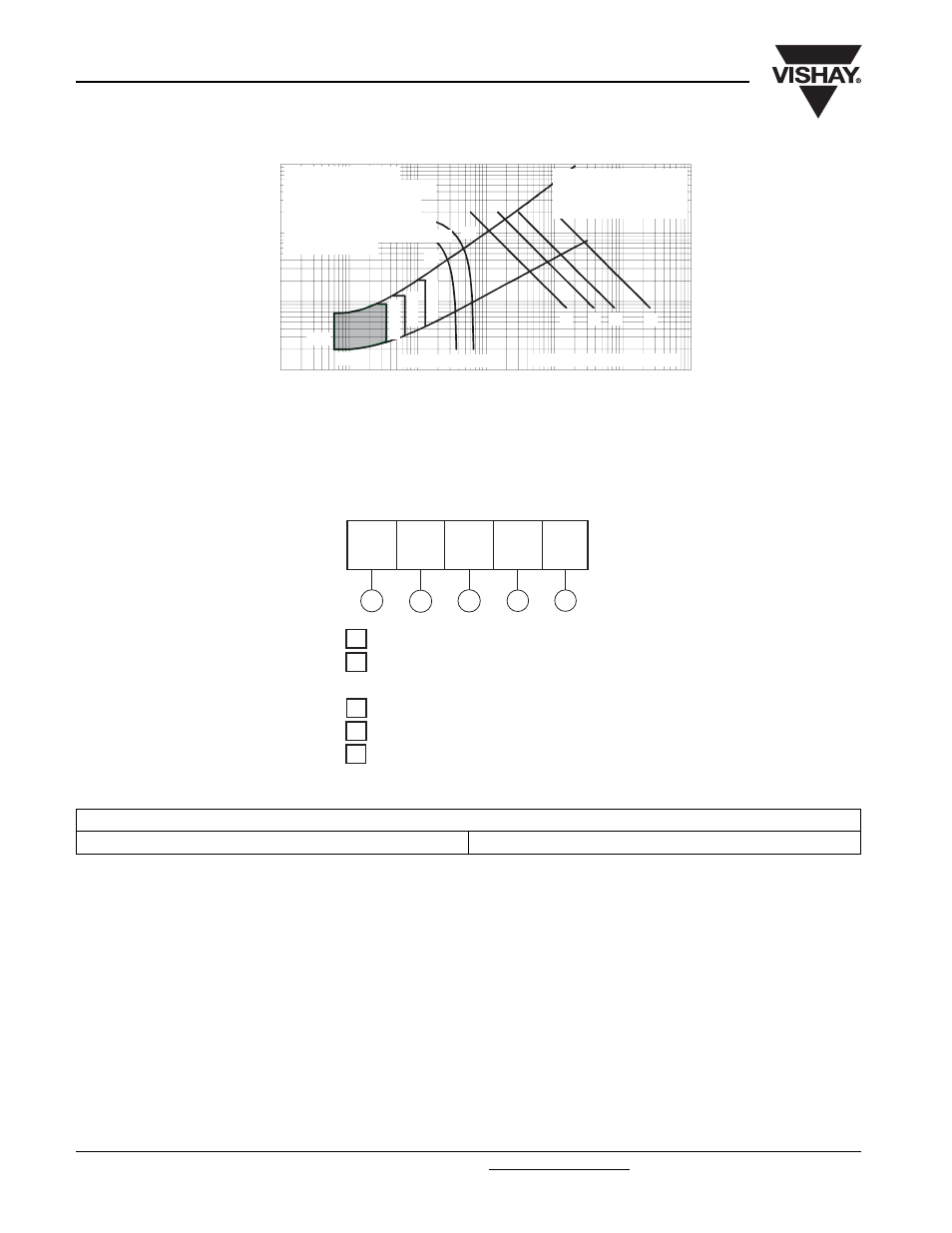
Fig. 9 - Gate Characteristics
ORDERING INFORMATION TABLE
0.1
1
10
100
0.001
0.01
0.1
1
10
100
1000
VGD
IGD
(b)
(a)
(1)
(3)
Instantaneous Gate Current (A)
In
st
a
n
tane
ou
s G
a
te
V
o
lt
ag
e
(
V
)
Rec tangular gate pulse
a) Recommended load line for
b) Recommended load line for
Frequency Limited by PG(AV)
Tj
=
2
5
°
C
Tj
=
-4
0
°
C
Tj
=
1
4
0
°
C
(2)
(1) PGM = 12W, tp = 5ms
(2) PGM = 30W, tp = 2ms
(3) PGM = 60W, tp = 1ms
(4) PGM = 200W, tp = 300µs
<=30% rated di/ dt: 15V, 40ohms
tr<=1 µs, tp=>6µs
Devic e: 181RKI Series
rated di/ dt: 20V, 30ohms;
tr<=0.5 µs, tp=>6µs
(4)
1
-
I
T(AV)
rated average output current (rounded/10)
2
-
0 = Eyelet terminals (gate and auxiliary cathode leads)
3
-
Thyristor
4
1 = Fast-on terminals (gate and auxiliary cathode leads)
-
Voltage code x 10 = V
RRM
(see Voltage Ratings table)
5
-
Lead (Pb)-free
Device code
5
1
3
2
4
18
1
RKI
100 PbF
LINKS TO RELATED DOCUMENTS
Dimensions
http://www.vishay.com/doc?95077