Vishay high power products, Phase control thyristors (stud version), 180 a – C&H Technology 181RKI...PbF Series User Manual
Page 5
www.vishay.com
For technical questions, contact: [email protected]
Document Number: 94382
4
Revision: 30-Apr-08
180RKI...PbF /181RKI...PbF Series
Vishay High Power Products
Phase Control Thyristors
(Stud Version), 180 A
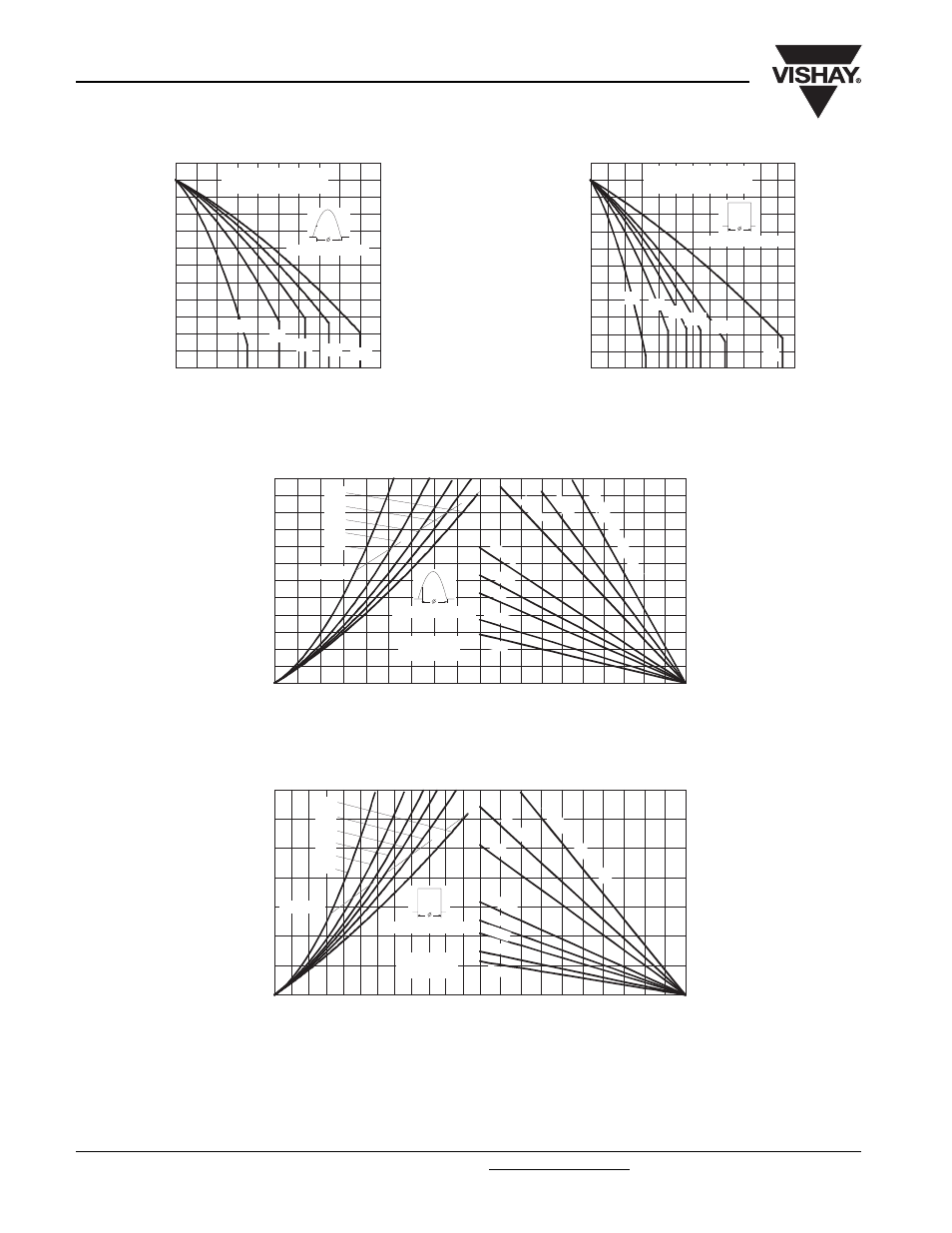
Fig. 1 - Current Ratings Characteristics
Fig. 2 - Current Ratings Characteristics
Fig. 3 - On-State Power Loss Characteristics
Fig. 4 - On-State Power Loss Characteristics
70
80
90
100
110
120
130
0
20 40 60 80 100 120 140 160 180 200
M
a
x
imu
m A
llo
w
a
b
le
Ca
se
T
e
mp
e
ra
tu
re
(°
C)
30°
60°
90°
120° 180°
Average On-state Current (A)
Cond uc tion Angle
181RKI Series
R
thJC
(DC) = 0.15 K/W
70
80
90
100
110
120
130
0
50
100
150
200
250
300
DC
30°
60°
90°
120°
180°
Average On-state Current (A)
Ma
x
im
u
m A
llo
w
a
b
le
C
a
se
T
e
m
p
e
ra
tu
re (
°C
)
Conduc tion Period
181RKI Series
R (DC) = 0.15 K/ W
thJC
0
25
50
75
100
125
Maximum Allowable Ambient Temperature (°C)
R
=
0
.1
K/
W
-
D
e
lta
R
th
SA
0
.2
K
/W
0.3
K/
W
0.6
K/W
0.8
K/ W
1 K/
W
1.5 K/
W
2 K/W
0
20
40
60
80
100
120
140
160
180
200
220
240
0
20
40
60
80 100 120 140 160 180
180°
120°
90°
60°
30°
RMS Limit
Conduc tion Angle
Ma
x
im
u
m
A
v
er
a
g
e
On-
st
a
te
P
o
w
e
r L
o
ss
(
W
)
Average On-state Current (A)
181RKI Series
T = 125°C
J
0
25
50
75
100
125
Maximum Allowable Ambient Temperature (°C)
R
=
0
.1
K
/ W
-
D
e
lta
R
th
SA
0.2
K/
W
0.3
K/W
0.6
K/ W
0.8
K/ W
1 K/W
1.5 K/W
2 K/ W
0
50
100
150
200
250
300
350
0
50
100
150
200
250
300
DC
180°
120°
90°
60°
30°
RMS Limit
Cond uc tion Period
Ma
x
im
u
m
A
v
e
ra
g
e
O
n
-s
ta
te
P
o
w
e
r L
o
ss
(
W
)
Average On-state Current (A)
181RKI Series
T = 125°C
J