Trench gate design dual igbtmod – C&H Technology CM400DU-12F User Manual
Page 2
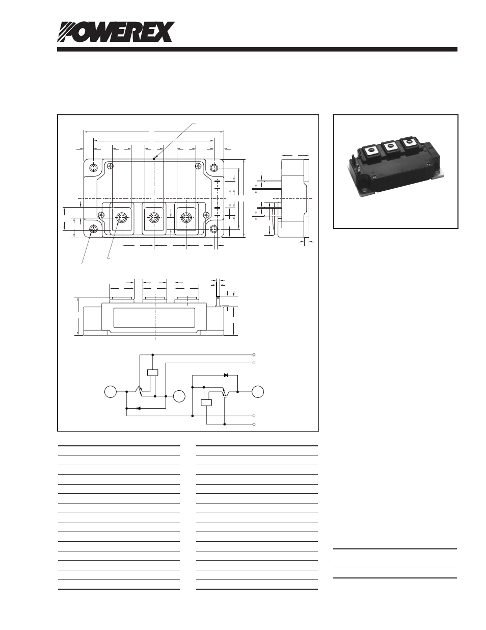
Trench Gate Design
Dual IGBTMOD™
400 Amperes/600 Volts
CM400DU-12F
Powerex, Inc., 173 Pavilion Lane, Youngwood, Pennsylvania 15697 (724) 925-7272
1
Rev. 12/09
Outline Drawing and Circuit Diagram
Description:
Powerex IGBTMOD™ Modules
are designed for use in switching
applications. Each module
consists of two IGBT Transistors
in a half-bridge configuration with
each transistor having a reverse-
connected super-fast recovery
free-wheel diode. All components
and interconnects are isolated
from the heat sinking baseplate,
offering simplified system
assembly and thermal
management.
Features:
£
Low Drive Power
£
Low VCE(sat)
£
Discrete Super-Fast Recovery
Free-Wheel Diode
£
Isolated Baseplate for Easy
Heat Sinking
Applications:
£
AC Motor Control
£
UPS
£
Battery Powered Supplies
Ordering Information:
Example: Select the complete
module number you desire from
the table - i.e. CM400DU-12F is a
600V (VCES), 400 Ampere Dual
IGBTMOD™ Power Module.
Current Rating
VCES
Type
Amperes
Volts (x 50)
CM
400
12
C2E1
RTC
RTC
E2
E1
G1
C1
E2
G2
G
H
H
U U
U
U
AC
AD
M
G2
E2
E1
G1
TC MEASUREMENT POINT
J E B
A
D
K
Y
Y
K
K
N
P
Q
Q
V
W
V
V
C
L
Y M
R
X
W
F
S - NUTS (3 TYP)
T - (4 TYP)
Z
AB
AA
LABEL
C2E1
C1
E2
Q
Dimensions
Inches
Millimeters
A
4.25
108.0
B
2.44
62.0
C
1.14+0.04/-0.01 29.0+1.0/-0.5
D
3.66±0.01
93.0±0.25
E
1.88±0.01
48.0±0.25
F
0.67
17.0
G
0.16
4.0
H
0.24
6.0
J
0.59
15.0
K
0.55
14.0
L
0.87
22.0
M
0.33
8.5
N
0.10
2.5
P
0.85
21.5
Dimensions
Inches
Millimeters
Q
0.98
25.0
R
0.11
2.8
S
M6 Metric
M6
T
0.26 Dia.
Dia. 6.5
U
0.002
0.5
V
0.71
18.0
W
0.28
7.0
X
0.16
4.0
Y
0.3
7.5
Z
0.325
8.25
AA
0.624
15.85
AB
0.709
18.0
AC
0.69
17.5
AD
1.012
25.7