Vishay high power products – C&H Technology 113MT..KPbF Series User Manual
Page 8
Document Number: 94353
For technical questions, contact: [email protected]
www.vishay.com
Revision: 29-Apr-08
7
53-93-113MT..KPbF Series
Three Phase Controlled Bridge
(Power Modules), 55 A to 110 A
Vishay High Power Products
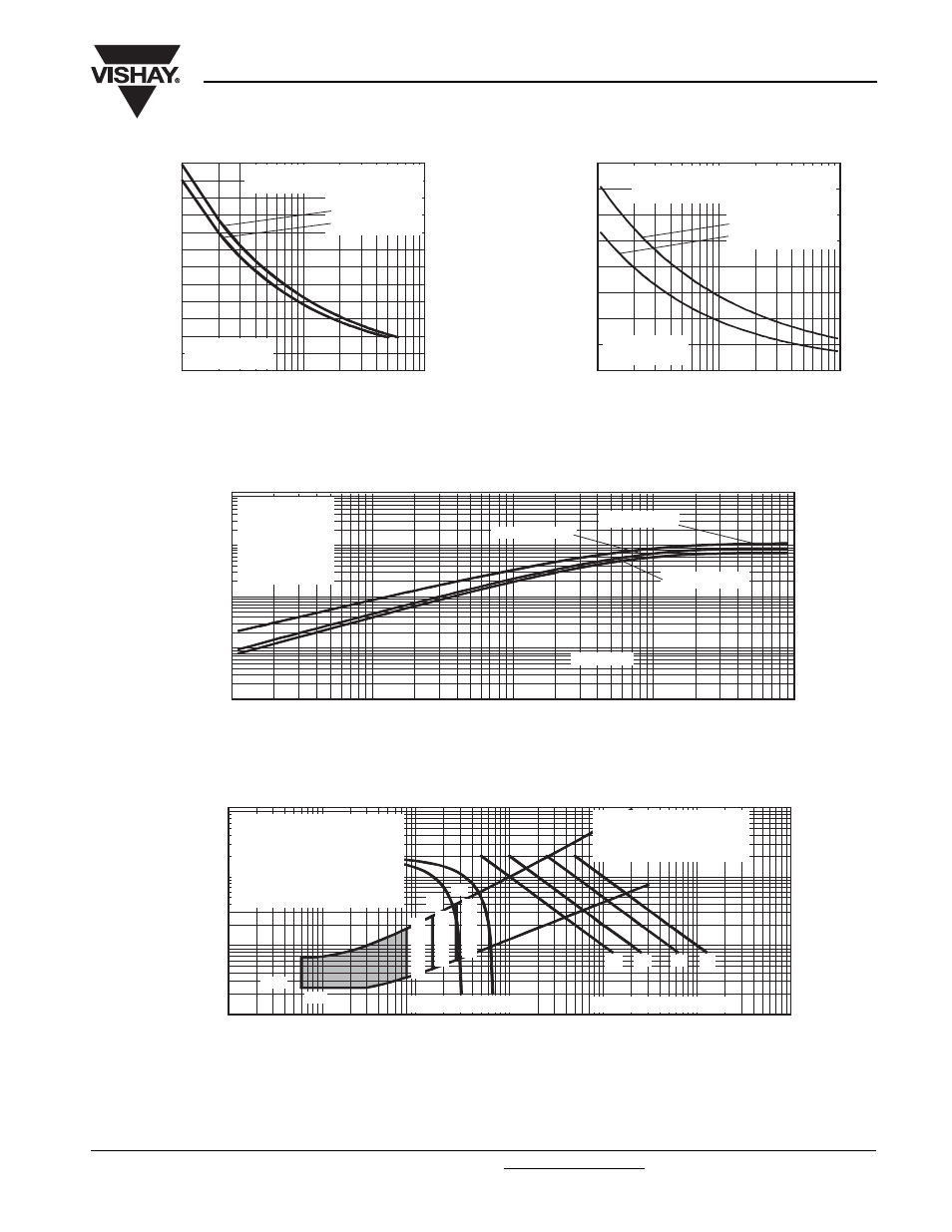
Fig. 14 - Maximum Non-Repetitive Surge Current
Fig. 15 - Maximum Non-Repetitive Surge Current
Fig. 16 - Thermal Impedance Z
thJC
Characteristics
Fig. 17 - Gate Characteristics
800
900
700
600
500
400
1000
Peak Half
S
ine Wave
On-
S
tate Current (A)
Number of Equal Amplitude
Half Cycle Current Pulses (N)
10
100
1
At any rated load condition and with
rated V
RRM
applied following surge.
113MT..K Series
Per junction
Initial T
J
= 125 °C
at 60 Hz 0.0083 s
at 50 Hz 0.0100 s
900
800
700
600
500
400
1200
1100
1000
Peak Half
S
ine Wave
On-
S
tate Current (A)
Pulse Train Duration (s)
0.01
0.1
1.0
113MT..K Series
Per junction
Maximum non-repetitive surge current
versus pulse train duration. Control
of conduction may not be maintained.
Initial T
J
= 125 °C
No voltage reapplied
Rated V
RRM
reapplied
0.001
0.01
0.1
1
10
0.001
0.01
0.1
1
Square Wave Pulse Duration (s)
Z
thJC
- Tran
s
ient Thermal
Impedance (K/W)
10
Per junction
53MT..K Series
113MT..K Series
93MT..K Series
Steady state value
R
thJC
= 1.07 K/W
R
thJC
= 0.86 K/W
R
thJC
= 0.70 K/W
(DC operation)
0.01
0.1
1
10
0.001
0.01
0.1
1
Instantaneous Gate Current (A)
In
s
tantaneou
s
Gate Volta
g
e (V)
1000
100
10
(b)
(a)
(4)
(3)
(2)
(1)
(1) PGM = 100 W, tp = 500 µs
(2) PGM = 50 W, tp = 1 ms
(3) PGM = 20 W, tp = 25 ms
(4) PGM = 10 W, tp = 5 ms
T
J
= -40 °C
T
J
= 25 °C
T
J
= 125 °C
VGD
IGD
Frequency Limited by PG(AV)
53/ 93/ 113MT..K Series
Rectangular gate pulse
a) Recommended load line for
rated dI/dt: 20 V, 30
Ω
tr = 0.5 µs, tp >= 6 µs
b) Recommended load line for
<=
30% rated dI/dt: 20 V, 65
Ω
tr = 1 µs, tp >= 6 µs