Vishay high power products, Phase control thyristors (stud version), 110 a, Ordering information table – C&H Technology 111RKI...PbF Series User Manual
Page 7
www.vishay.com
For technical questions, contact:
Document Number: 94379
6
Revision: 04-Nov-09
110RKI...PbF, 111RKI...PbF Series
Vishay High Power Products
Phase Control Thyristors
(Stud Version), 110 A
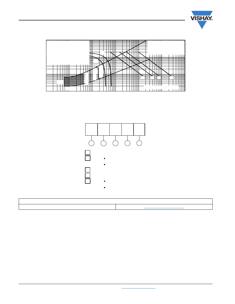
Fig. 9 - Gate Characteristics
ORDERING INFORMATION TABLE
0.1
1
10
100
0.001
94379_09
Instantaneous Gate Current (A)
Instantaneous
G
ate Voltage (V)
0.01
0.1
1
10
1000
100
(1) P
GM
= 12 W, t
p
= 5 ms
(2) P
GM
= 30 W, t
p
= 2 ms
(3) P
GM
= 60 W, t
p
= 1 ms
(4) P
GM
= 200 W, t
p
= 300 μs
Rectangular gate pulse
(a) Recommended load line for
rated dI/dt: 20 V, 30
Ω,
t
r
≤ 0.5 μs, t
p
≥ 6 μs
(b) Recommended load line for
≤ 30 % rated dI/dt: 15 V, 40
Ω,
t
r
≤ 1 μs, t
p
≥ 6 μs
(b)
(a)
T
J
= 25 °C
T
J
= 140 °C
T
J
= 40 °C
V
GD
I
GD
(1)
(2)
(3)
(4)
Frequency limited by P
G(AV)
Device code
5
1
3
2
4
11
0
RKI
120 PbF
1
-
I
T(AV)
rated average output current (rounded/10)
3
-
Thyristor
4
-
Voltage code x 10 = V
RRM
(see Voltage Ratings table)
5
-
None = Standard production
PbF = Lead (Pb)-free
2
-
0 = Eyelet terminals (gate and auxiliary cathode leads)
1 = Fast-on terminals (gate and auxiliary cathode leads)
LINKS TO RELATED DOCUMENTS
Dimensions
www.vishay.com/doc?95003