Vishay high power products, Phase control thyristors (stud version), 110 a – C&H Technology 111RKI...PbF Series User Manual
Page 6
Document Number: 94379
For technical questions, contact:
www.vishay.com
Revision: 04-Nov-09
5
110RKI...PbF, 111RKI...PbF Series
Phase Control Thyristors
(Stud Version), 110 A
Vishay High Power Products
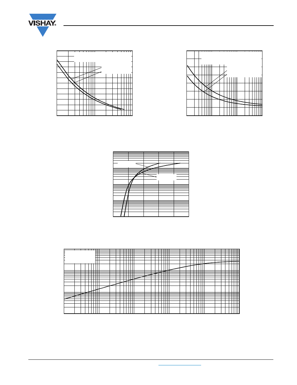
Fig. 5 - Maximum Non-Repetitive Surge Current
Fig. 6 - Maximum Non-Repetitive Surge Current
Fig. 7 - On-State Voltage Drop Characteristics
Fig. 8 - Thermal Impedance Z
thJC
Characteristic
Peak Half
S
ine Wave
On-
S
tate Current (A)
Number of Equal Amplitude Half
Cycle Current Pulses (N)
10
100
1
800
1000
1200
1800
1600
1400
2000
94379_05
At any rated load condition and with
rated V
RRM
applied following surge.
Initial T
J
= 140 °C
at 60 Hz 0.0083 s
at 50 Hz 0.0100 s
Peak Half
S
ine Wave
On-
S
tate Current (A)
Pulse Train Duration (s)
0.1
10
1
0.01
500
1000
1500
2000
2500
94379_06
Maximum non-repetitive surge current
versus pulse train duration. Control of
conduction may not be maintained.
Initial T
J
= 140 °C
No voltage reapplied
Rated V
RRM
reapplied
Instantaneous On-
S
tate Current (A)
Instantaneous On-State Voltage (V)
0
1
2
3
4
5
1
100
10
10 000
1000
94379_07
T
J
= 140 °C
T
J
= 25 °C
0.001
0.01
0.1
1
0.0001
0.001
0.01
0.1
1
10
Square Wave Pulse Duration (s)
Z
thJC
- Transient Thermal
Impe
d
ance (K/W)
94379_08
Steady state value
R
thJC
= 0.27 K/W
(DC operation)