Vishay high power products, Phase control thyristors (stud version), 110 a – C&H Technology 111RKI...PbF Series User Manual
Page 4
Document Number: 94379
For technical questions, contact:
www.vishay.com
Revision: 04-Nov-09
3
110RKI...PbF, 111RKI...PbF Series
Phase Control Thyristors
(Stud Version), 110 A
Vishay High Power Products
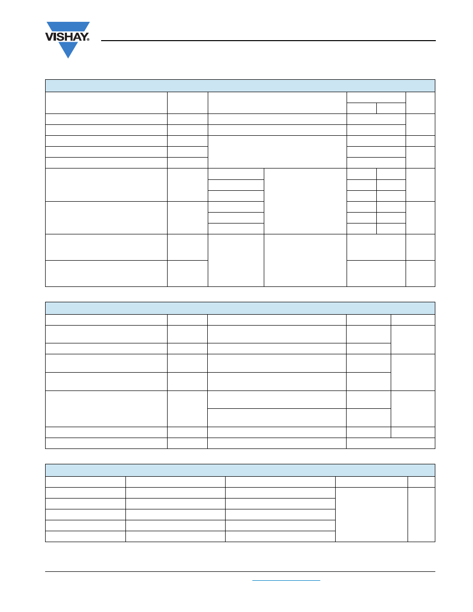
Note
• The table above shows the increment of thermal resistance R
thJC
when devices operate at different conduction angles than DC
TRIGGERING
PARAMETER SYMBOL
TEST
CONDITIONS
VALUES
UNITS
TYP.
MAX.
Maximum peak gate power
P
GM
T
J
= T
J
maximum, t
p
≤ 5 ms
12
W
Maximum average gate power
P
G(AV)
T
J
= T
J
maximum, f = 50 Hz, d% = 50
3.0
Maximum peak positive gate current
I
GM
T
J
= T
J
maximum, t
p
≤ 5 ms
3.0
A
Maximum peak positive gate voltage
+ V
GM
20
V
Maximum peak negative gate voltage
- V
GM
10
DC gate current required to trigger
I
GT
T
J
= - 40 °C
Maximum required gate
trigger/current/voltage are
the lowest value which will
trigger all units 12 V anode
to cathode applied
180
-
mA
T
J
= 25 °C
80
120
T
J
= 140 °C
40
-
DC gate voltage required to trigger
V
GT
T
J
= - 40 °C
2.5
-
V
T
J
= 25 °C
1.6
2
T
J
= 140 °C
1
-
DC gate current not to trigger
I
GD
T
J
= T
J
maximum
Maximum gate current/
voltage not to trigger is the
maximum value which will
not trigger any unit with
rated V
DRM
anode to
cathode applied
6.0
mA
DC gate voltage not to trigger
V
GD
0.25
V
THERMAL AND MECHANICAL SPECIFICATIONS
PARAMETER SYMBOL
TEST
CONDITIONS
VALUES
UNITS
Maximum operating junction
temperature range
T
J
- 40 to 140
°C
Maximum storage temperature range
T
Stg
- 40 to 150
Maximum thermal resistance,
junction to case
R
thJC
DC operation
0.27
K/W
Maximum thermal resistance,
case to heatsink
R
thCS
Mounting surface, smooth, flat and greased
0.1
Mounting torque, ± 10 %
Non-lubricated threads
15.5
(137)
N · m
(lbf · in)
Lubricated threads
14
(120)
Approximate weight
130
g
Case style
See dimensions - link at the end of datasheet
TO-209AC (TO-94)
ΔR
thJC
CONDUCTION
CONDUCTION ANGLE
SINUSOIDAL CONDUCTION
RECTANGULAR CONDUCTION
TEST CONDITIONS
UNITS
180°
0.043
0.031
T
J
= T
J
maximum
K/W
120°
0.052
0.053
90°
0.066
0.071
60°
0.096
0.101
30°
0.167
0.169