Vsk.430..pbf series, Vishay high power products, Power modules) – C&H Technology VSK.430..PbF Series User Manual
Page 6
Document Number: 93748
For technical questions, contact: [email protected]
www.vishay.com
Revision: 02-Apr-08
5
VSK.430..PbF Series
Thyristor/Diode and Thyristor/Thyristor, 430 A
(SUPER MAGN-A-PAK
TM
Power Modules)
Vishay High Power Products
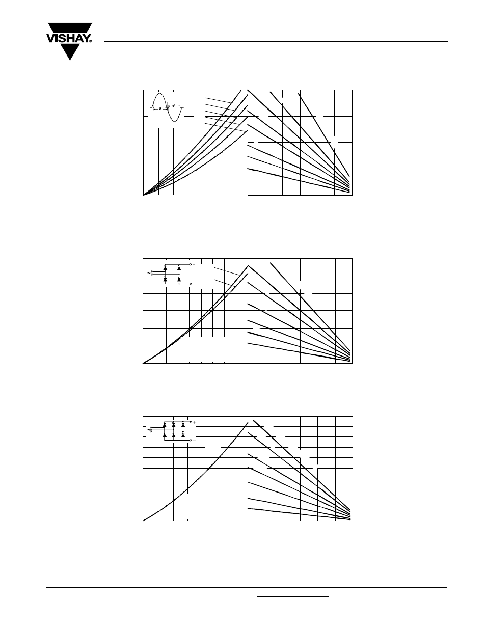
Fig. 7 - On-State Power Loss Characteristics
Fig. 8 - On-State Power Loss Characteristics
Fig. 9 - On-State Power Loss Characteristics
0
20
40
60
80
100
120
Maximum Allowable Ambient Temperature (°C)
R
=
0
.0
5
K
/ W
-
D
e
lta
R
th
SA
0
.09
K
/ W
0.1
2
K/
W
0.1
6
K/W
0.2
K/ W
0.3
K/W
0.4
K/ W
0.6 K/ W
0
100
200
300
400
500
600
700
800
0
100
200
300
400
500
600
700
180°
120°
90°
60°
30°
Total RMS Output Current (A)
M
a
x
imu
m
T
o
ta
l O
n
-s
ta
te
P
o
w
e
r L
o
s
s
(W
)
Conduction Angl e
VSK.430..PbF Series
Per Module
T = 130°C
J
0
20
40
60
80
100
120
Maximum Allowable Ambient Temperature (°C )
R
=
1
K
/W
- D
e
lta
R
th
SA
1.5
K/
W
2
K/
W
3 K
/ W
5 K
/ W
10 K/W
15 K/ W
0
500
1000
1500
2000
2500
3000
0
100 200 300 400 500 600 700 800 900
Total Output Current (A)
M
a
x
im
u
m
T
o
ta
l P
o
we
r Lo
ss (
W
)
180°
(Sine)
180°
(Rect)
2 x VSK.430..PbF Series
Single Phase Bridge
Connected
T = 130 °C
J
0
20
40
60
80
100
120
Maximum Allowable Ambient Temperature (°C)
R
=
0.0
05
K/
W
- D
e lt
a
R
th
SA
0.0
1
K/
W
0.0
2 K
/W
0.03
K/ W
0.05
K/ W
0.1 K/W
0.2 K/ W
0
500
1000
1500
2000
2500
3000
3500
4000
4500
5000
0
200
400
600
800 1000 1200 1400
Total Output Current (A)
M
a
x
im
u
m
T
o
ta
l
P
o
we
r Lo
ss (
W
)
120°
(Rect)
3 x VSK.430..PbF Series
Three Phase Bridge
Connected
T = 130°C
J