Cpv362m4fpbf, Vishay high power products, Igbt sip module (fast igbt) – C&H Technology CPV362M4FPbF User Manual
Page 4
Document Number: 94361
For technical questions, contact: [email protected]
www.vishay.com
Revision: 29-Apr-08
3
CPV362M4FPbF
IGBT SIP Module
(Fast IGBT)
Vishay High Power Products
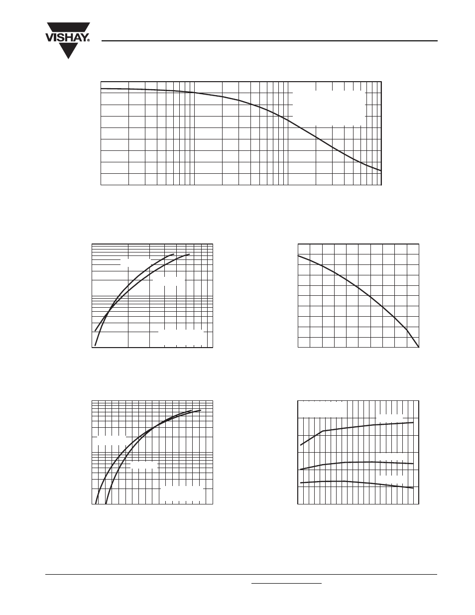
Fig. 1 - Typical Load Current vs. Frequency
(Load Current = I
RMS
of Fundamental)
Fig. 2 - Typical Output Characteristics
Fig. 3 - Typical Transfer Characteristics
Fig. 4 - Maximum Collector Current vs.
Case Temperature
Fig. 5 - Typical Collector to Emitter Voltage vs.
Junction Temperature
0
4
3
2
1
5
6
7
8
9
0.1
1
f - Frequency (kHz)
Load Current (A)
100
0.00
0.29
0.58
0.88
1.17
1.46
1.75
2.05
2.34
2.63
10
T
C
= 90 °C
T
J
= 125 °C
Power factor = 0.8
Modulation depth = 1.15
V
CC
= 50 % of rated voltage
Total Output Power (kW)
1
100
10
I
C
- Collector to Ermitter Current (A)
V
CE
- Collector to Emitter Voltage (V)
10
1
V
GE
= 15 V
20 µs pulse width
T
J
= 25 °C
T
J
= 150 °C
1
100
10
I
C
- Collector to Emitter Current (A)
V
GE
- Gate to Emitter Voltage (V)
6
7
8
9
10
11
12
13
14
5
V
CC
= 50 V
5 µs pulse width
T
J
= 25 °C
T
J
= 150 °C
0
2
4
6
8
10
Maximum DC Collector Current (A)
T
C
- Case Temperature (°C)
25
50
75
100
125
150
1.0
2.0
1.5
2.5
V
CE
- Collector to Emitter Voltage (V)
T
J
- Junction Temperature (°C)
- 60 - 40 - 20 0
20 40 60 80 100 120 140 160
V
GE
= 15 V
80 µs pulse width
I
C
= 9.6 A
I
C
= 4.8 A
I
C
= 2.4 A