Vsk.71.. series, Vishay high power products – C&H Technology VSK.71.. Series User Manual
Page 5
www.vishay.com
For technical questions, contact: [email protected]
Document Number: 94626
4
Revision: 17-Dec-08
VSK.71.. Series
Vishay High Power Products
ADD-A-PAK Generation VII Power Modules
Standard Diodes, 80 A
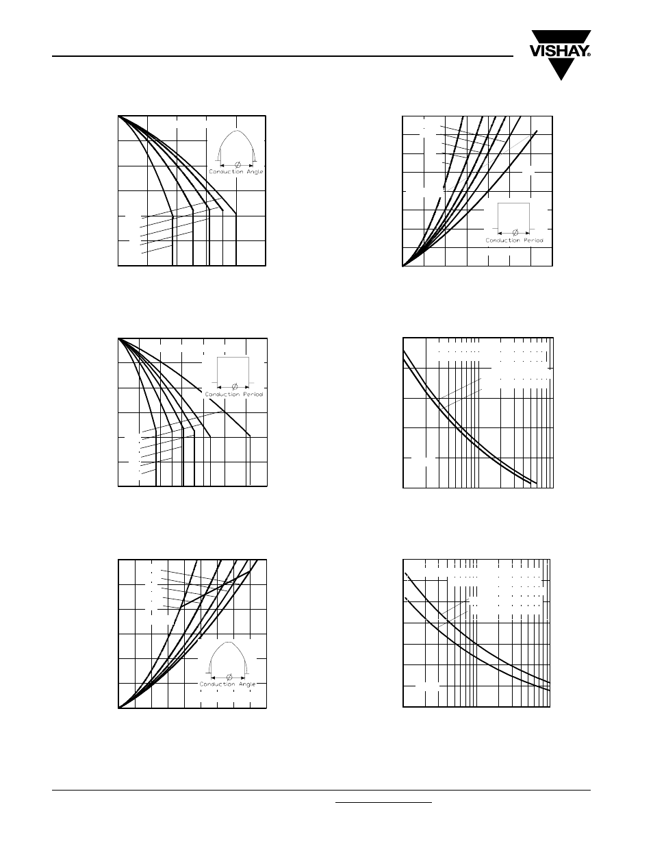
Fig. 1 - Current Ratings Characteristics
Fig. 2 - Current Ratings Characteristics
Fig. 3 - Forward Power Loss Characteristics
Fig. 4 - Foward Power Loss Characteristics
Fig. 5 - Maximum Non-Repetitive Surge Current
Fig. 6 - Maximum Non-Repetitive Surge Current
Average forward current (A)
Maximum allowable case temperature (°C)
0
20
40
60
80
100
90
100
110
120
130
140
150
180°
120°
90°
60°
30°
RthJC (DC) = 0.28°C/W
0
20
40
60
80
100 120 140
90
100
110
120
130
140
150
180°
120°
90°
60°
30°
DC
RthJC (DC) = 0.28°C/W
Average forward current (A)
Maximum allowable case temperature (°C)
Average forward current (A)
Maximum average forward power loss (W)
0
10 20 30 40 50 60 70 80 90
0
20
40
60
80
100
120
180°
120°
90°
60°
30°
RMS limit
Per leg, Tj = 150°C
Average forward current (A)
Maximum average forward power loss (W)
0
20
40
60
80
100 120 140
0
20
40
60
80
100
120
140
160
180°
120°
90°
60°
30°
RMS limit
DC
Per leg, Tj = 150°C
Peak half sine wave forward current (A)
Number of equal amplitude half cycle current pulses (N)
1
10
100
400
600
800
1000
1200
1400
At any rated load condition and with
rated Vrrm applied following surge
Initial Tj = Tj max
@ 60 Hz 0.0083 s
@ 50 Hz 0.0100s
Per leg
Peak half sine wave forward current (A)
Pulse train duration (s)
0.01
0.1
1
200
400
600
800
1000
1200
1400
1600
Maximum Non-repetitive Surge Current
Versus Pulse Train Duration
Initial Tj = 150°C
No Voltage Reapplied
Rated Vrrm reapplied
Per leg