Vsk.71.. series, Vishay high power products – C&H Technology VSK.71.. Series User Manual
Page 4
Document Number: 94626
For technical questions, contact: [email protected]
www.vishay.com
Revision: 17-Dec-08
3
VSK.71.. Series
ADD-A-PAK Generation VII Power Modules
Standard Diodes, 80 A
Vishay High Power Products
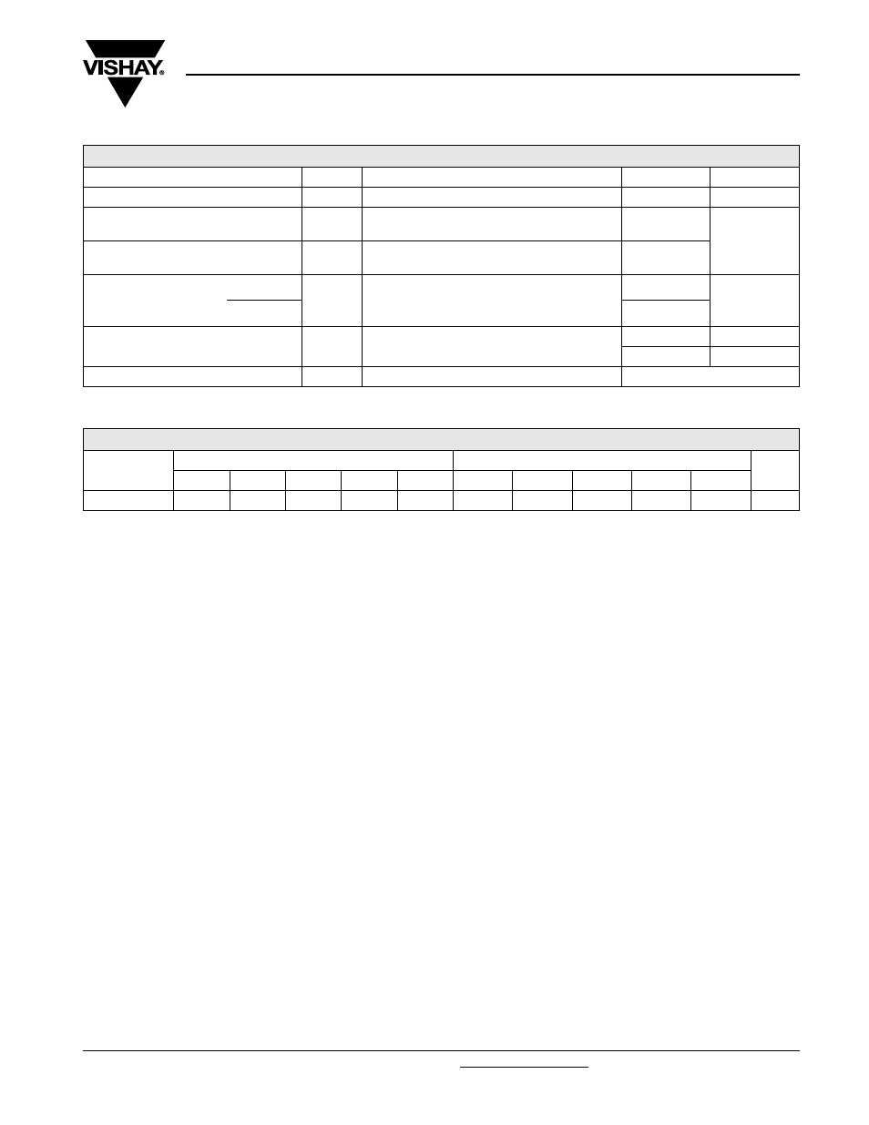
Note
• Table shows the increment of thermal resistance R
thJC
when devices operate at different conduction angles than DC
THERMAL AND MECHANICAL SPECIFICATIONS
PARAMETER
SYMBOL
TEST CONDITIONS
VALUES
UNITS
Junction and storage temperature range
T
J
, T
Stg
- 40 to 150
°C
Maximum internal thermal resistance,
junction to case per leg
R
thJC
DC operation
0.28
°C/W
Typical thermal resistance,
case to heatsink per module
R
thCS
Mounting surface flat, smooth and greased
0.1
Mounting torque ± 10 %
to heatsink
A mounting compound is recommended and the
torque should be rechecked after a period of
3 hours to allow for the spread of the compound.
4
Nm
busbar
3
Approximate weight
75
g
2.7
oz.
Case style
JEDEC
TO-240AA compatible
ΔR CONDUCTION PER JUNCTION
DEVICES
SINE HALF WAVE CONDUCTION
RECTANGULAR WAVE CONDUCTION
UNITS
180°
120°
90°
60°
30°
180°
120°
90°
60°
30°
VSK.71
0.075
0.088
0.113
0.155
0.228
0.06
0.094
0.12
0.158
0.23
°C/W