Vishay high power products – C&H Technology GA75TS12UPbF User Manual
Page 7
www.vishay.com
For technical questions, contact: [email protected]
Document Number: 94427
6
Revision: 18-Jan-08
GA75TS120UPbF
Vishay High Power Products
"Half-Bridge" IGBT INT-A-PAK
(Ultrafast Speed IGBT), 75 A
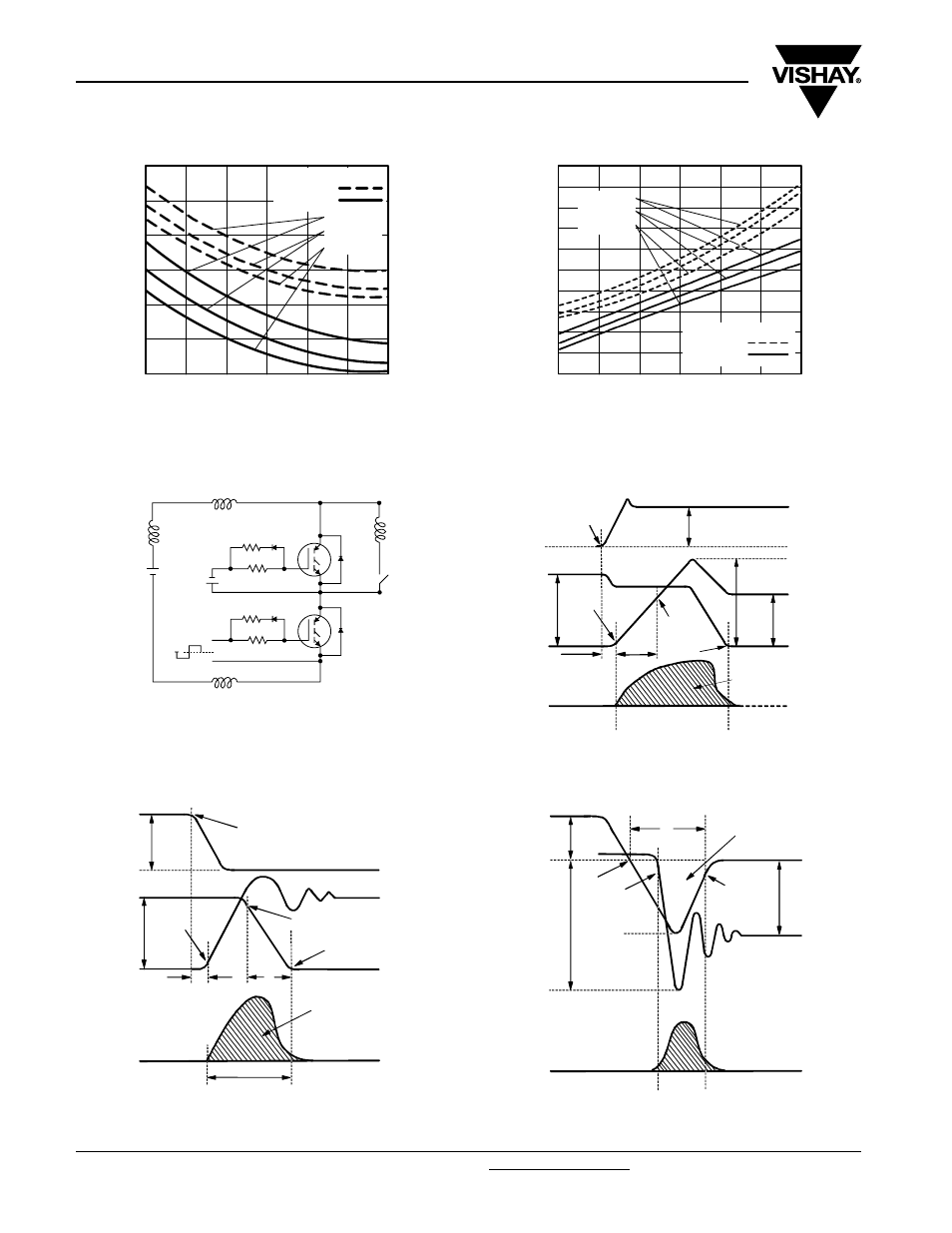
Fig. 15 - Typical Reverse Recovery Time vs. dI
F
/dt
Fig. 16 - Typical Recovery Current vs. dI
F
/dt
Fig. 17a - Test Circuit for Measurement of I
LM
, E
on
, E
off(diode)
, t
rr
, Q
rr
,
I
rr
, t
d(on)
, t
r
, t
d(off)
, t
f
Fig. 17b - Test Waveforms for Circuit of Fig. 18a,
Defining E
off
, t
d(off)
, t
f
Fig. 17c - Test Waveforms for Circuit of Fig. 18a,
Defining E
on
, t
d(on)
, t
r
Fig. 17d - Test Waveforms for Circuit of Fig. 18a,
Defining E
rec
, t
rr
, Q
rr
, I
rr
500
1000
1500
2000
100
150
200
250
dI
F
/dt (A/µs)
t
rr
(ns)
V
R
= 720 V
T
J
= 125 °C
T
J
= 25 °C
I
F
= 150 A
I
F
= 75 A
I
F
= 37 A
500
1000
1500
2000
0
40
120
200
dI
F
/dt (A/µs)
I
RRM
(A)
V
R
= 720 V
T
J
= 125 °C
T
J
= 25 °C
I
F
= 150 A
I
F
= 75 A
I
F
= 37 A
80
160
L2
L1
V
CC
L
R
G2
R
G1
R
G2
R
G1
+ V
G2
- V
G2
+
-
+
-
L3
V
CC
= 60 % of BV
CES
LS = L1 + L2 + L3
V
GE
= ± 15 V
t1
I
C
V
CE
t1
t2
90 % I
C
10 % V
CE
t
d(off)
t
f
I
C
5 % I
C
t1 + 5 µs
Vce ic dt
90 % V
GE
+ V
GE
∫
E
off
=
V
CE
I
C
dt
∫
t2
t1
5 % V
CE
I
C
I
pk
V
CC
10 % I
C
V
CE
t1
t2
D.U.T. voltage
and current
Gate voltage D.U.T.
+ V
G
10 % + V
G
90 % I
C
t
r
t
d(on)
E
on
=
V
CE
I
C
dt
Diode reverse
recovery energy
t
x
∫
E
rec
=
t4
t3
t4
t3
Diode recovery
waveforms
I
C
V
pk
10 % V
CC
I
rr
10 % I
rr
V
CC
t
rr
∫
Q
rr
=
t
rr
t
x
id dt
V
D
I
C
dt
I
C
dt