Rtop, Vishay sfernice – C&H Technology RTOP User Manual
Page 5
Document Number: 50045
For technical questions, contact: [email protected]
www.vishay.com
Revision: 14-Nov-08
4
RTOP
Power Resistor for Mounting onto a Heatsink
Thick Film Technology
Vishay Sfernice
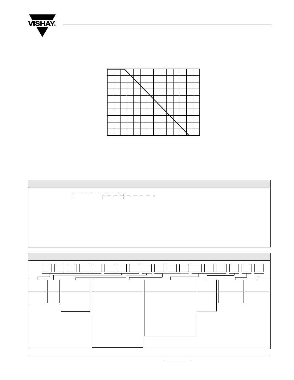
POWER RATING CHART
The temperature of the heater should be maintained in the limit specified. To improve the thermal conductivity, surfaces in
contact should be laid on with a silicon grease and the torque applied on the screw for tightening should be around 2 Nm.
MARKING
Series, style, ohmic value (in), tolerance (in %), manufacturing date, VISHAY trade mark.
PACKAGING
Box of 10 units
% RA
TED PO
WER
0
20
40
60
80
100
120
140
HEATSINK TEMPERATURE IN DEGREES CELSIUS
0
20
40
60
80
100
ORDERING INFORMATION
RTOP
200
5U
± 1 %
± %
V
DRTOP
50
150U
5 %
15U
5 %
V
XXX
BO10
e
R1 T1 R2
MODEL
STYLE
OHMIC
VALUE
ABSOLUTE TOLERANCE PER
RESISTOR
CONNECTIONS
CUSTOM
DESIGN
PACKAGING
LEAD
(Pb)-FREE
RTOP
DRTOP
100
50
Optional
± 1 %
± 2 %
± 5 %
± 10 %
To be precise
for each
resistor
V: Screw
VS: RTOP Shunt
Optional
GLOBAL PART NUMBER INFORMATION
GLOBAL
MODEL
SIZE
LEADS
OHMIC VALUE
OHMIC VALUE
TOL.
PACKAGING
SPECIAL
RTOP
DRTOP
100
200
F = Faston type
V = Screw
VS, FS =
RTOP Shunt
If RTOP: The first three
digits are significant figures
and the last digit specifies
the number of zeros to
follow.
R designates decimal point.
48R7 = 48.7
Ω
4871 = 4870
Ω
1002 = 10 000
Ω
R010 = 0.01
Ω
R680 = 0.68
Ω
2700 = 2700
Ω = 2K7 Ω
Blank if RTOP.
If DRTOP: The first two
digits are significant figures
and the last digit specifies
the number of zeros to
follow.
R designates decimal point.
48R = 48
Ω
487 = 487
Ω
F = 1 %
G = 2 %
J = 5 %
K = 10 %
B = Box
10 pieces
As applicable
Ex = UA1
O
P
1
0
0
V
5
0
R
K
R
T
D
R
5
0
B