Rtop, Vishay sfernice – C&H Technology RTOP User Manual
Page 3
Document Number: 50045
For technical questions, contact: [email protected]
www.vishay.com
Revision: 14-Nov-08
2
RTOP
Power Resistor for Mounting onto a Heatsink
Thick Film Technology
Vishay Sfernice
Note
(1)
MIL STD 202 Method 301
PERFORMANCE
TESTS
CONDITIONS
REQUIREMENTS
Momentary Overload
NF EN 140000 CEI 115_1
2.5 Pn/5 s
U
S
< 2
U
L
< ± (0.25 % + 0.05
Ω)
Rapid Temperature Change
NF EN 140000 CEI 68214 Test Na
5 cycles - 55 °C + 125 °C
< ± (0.25 % + 0.05
Ω)
Load Life
NF EN 140000 CEI 115_1
Pn at 25 °C 1000 h
< ± (0.5 % + 0.05
Ω)
Humidity (Steady State)
MIL STD 202 Method 103 B Test D
56 days 95 % R.H.
< ± (0.5 % + 0.05
Ω)
SPECIAL FEATURES
MODEL
RTOP 200
RTOP 100
DRTOP 100
DRTOP 50
Power Rating at + 25 °C
Chassis Mounted Resistors
Unmounted Resistors
200 W
5 W
100 W
5 W
100 W
3.5 W
50 W
3.5 W
Thermal Resistance (Per Resistor)
0.5 °C/W
1 °C/W
0.5 °C/W
1 °C/W
Limiting Voltage
U
L
1500 V
1500 V
500 V
500 V
Dielectric Strength
(1)
Connections/Chassis
2500 V, 1 min
10 mA max.
2500 V, 1 min
10 mA max.
2500 V, 1 min
10 mA max.
2500 V, 1 min
10 mA max.
Dielectric Strength
(1)
Connections/Resistors
- -
2500 V, 1 min
10 mA max.
2500 V, 1 min
10 mA max.
Ohmic Value Range
0.046 to 1 M
Ω
0.092 to 1 M
Ω
Tolerance
± 1 % to ± 10 %
± 1 % to ± 10 %
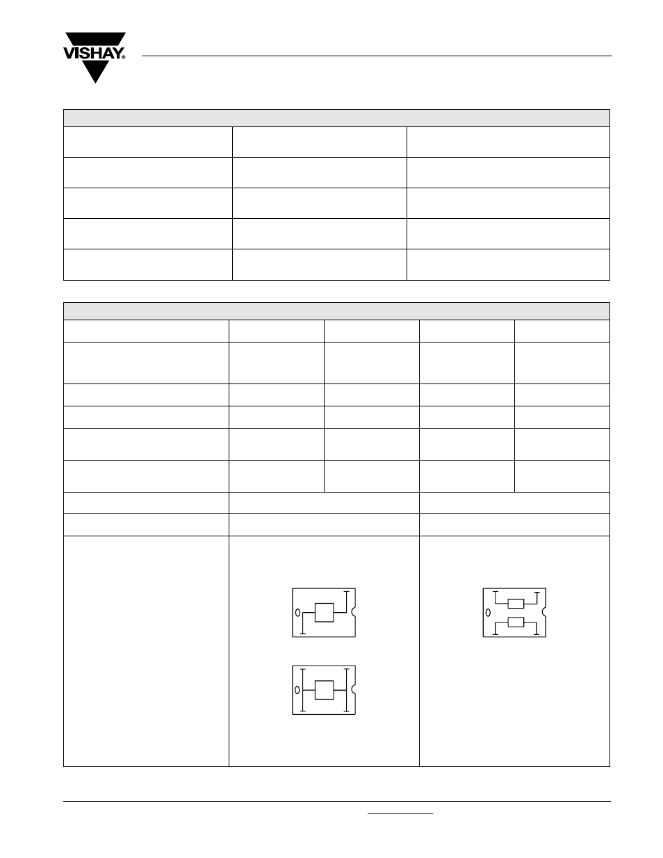
Electrical Diagrams
R
R
Shunt Version
R2
R1