Vishay high power products – C&H Technology GA200SA60SP User Manual
Page 4
Document Number: 94363
For technical questions, contact: [email protected]
www.vishay.com
Revision: 29-Apr-08
3
GA200SA60SP
Insulated Gate Bipolar Transistor
(Standard Speed IGBT), 100 A
Vishay High Power Products
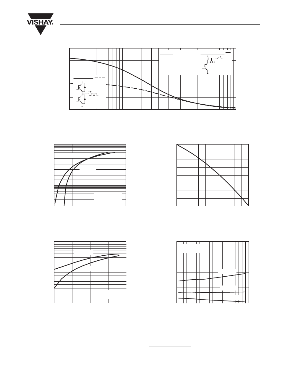
Fig. 1 - Typical Load Current vs. Frequency
(Load Current = I
RMS
of Fundamental)
Fig. 2 - Typical Output Characteristics
Fig. 3 - Typical Transfer Characteristics
Fig. 4 - Maximum Collector Current vs. Case Temperature
Fig. 5 - Typical Collector to Emitter Voltage vs.
Junction Temperature
For both:
Duty cycle: 50 %
T
J
= 125 °C
T
sink
= 90 °C
Gate drive as specified
Power dissipation = 140 W
0
250
0.1
f - Frequency (kHz)
Load Current (A)
1
10
100
200
150
100
50
Clamp voltage:
80 % of rated
Triangular wave:
I
60 % of rated
voltage
Ideal diodes
Square wave:
I
1
10
100
1000
0.5
1.0
1.5
2.0
2.5
V
CE
- Collector to Emitter Voltage (V)
I
C
- Collector to Emitter Current (A)
V
GE
= 15 V
20 µs pulse width
T
J
= 150 °C
T
J
= 25 °C
10
100
1000
5
6
7
V
GE
- Gate to Emitter Voltage (V)
I
C
- Collector to Emitter Current (A)
T
J
= 150 °C
T
J
= 25 °C
V
CC
= 50 V
5 µs pulse width
0
100
150
200
50
25
50
75
100
125
150
T
C
- Case Temperature (°C)
Maximum DC Collector Current (A)
1
2
3
- 60 - 40 - 20 0
20 40 60 80 100 120 140 160
T
J
- Junction Temperature (°C)
V
CE
- Collector to Emitter Voltage (V)
V
GE
= 15 V
80 µs pulse width
I
C
= 400 A
I
C
= 200 A
I
C
= 100 A