3 function chart "point level – VEGA VEGATOR 112 User Manual
Page 14
14
6 Setup
VEGATOR 112 •
46106-EN-131217
a mechanical switch, e.g. a float switch, is to be connected, the line
monitoring must be deactivated because only the switching condi-
tions "open" or "closed" can be delivered.
When level switches VEGASWING/VEGAVIB/VEGAWAVE in two-wire
version are connected, a function test can be carried out. The test key
is recessed behind the front plate of the signal conditioning instru-
ment. Press the test key for at least one second with a suitable object
(screwdriver, pen, etc.).
Pushing the test key interrupts the circuit to the sensor and triggers a
restart of the sensor. The statuses fault signal, full signal (1.2 mA) and
empty signal (2.1 mA) are thus simulated. Check if a fault signal (red
signal lamp) is triggered when the test key is pressed and then a full
signal and subsequent empty signal (yellow signal lamp) after the key
is released. Please note that when line monitoring is deactivated, the
red signal lamp does not light up.
Note:
Keep in mind that downstream connected devices are activated dur-
ing the function test. This allows you to check the correct function of
the measuring system.
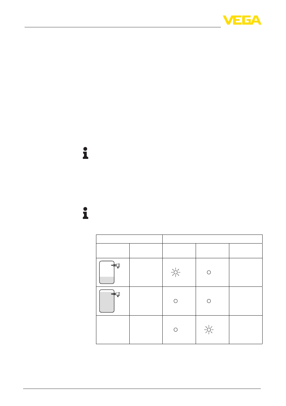
6.3 Function chart "Point level"
The following chart provides an overview of the switching conditions
depending on the set mode and the level.
Note:
The switching conditions in the tables are only valid if the mode
switch on the sensor is set to "Max.".
Sensor
Signal conditioning instrument
Level
Sensor cur-
rent
LED yellow
(output)
LED red (fail-
ure)
Relay
approx.
2.1 mA
ON
approx.
1.2 mA
OFF
any
< 0.35 mA
> 6.8 mA
OFF
Test key
Overfill protection, point
level