VEGA VEGATOR 112 User Manual
Page 13
13
6 Setup
VEGATOR 112 •
46106-EN-131217
•
Yellow
– Relay control lamp
– The yellow relay control lamp reacts depending on the set
mode
– The relay control lamp generally indicates the activated (ener-
gized) condition of the relay
– A dark relay control lamp means that the relay is deenergised
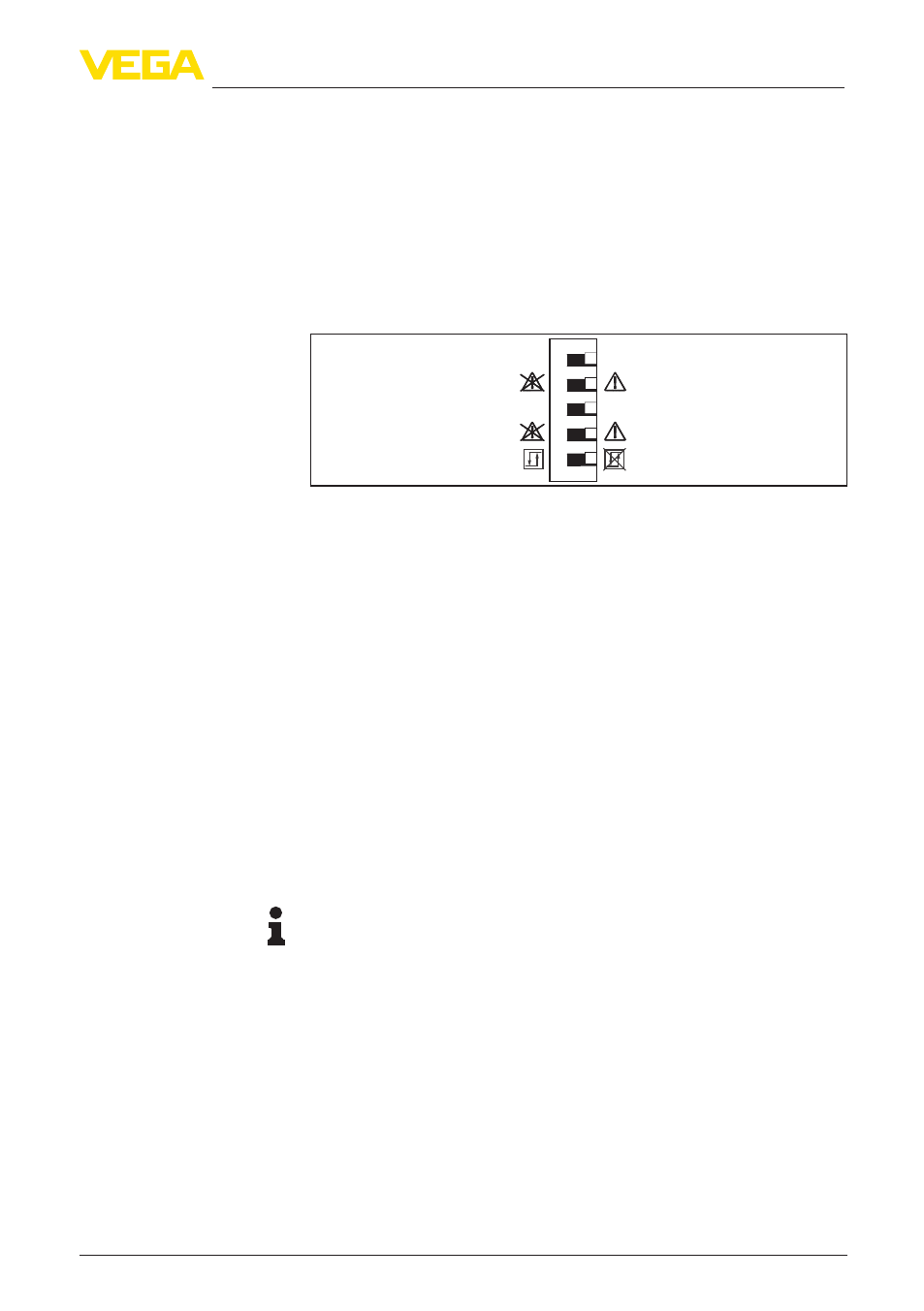
The DIL switch block is located behind the front cover. The individual
switches are assigned as follows:
3
4
5
max
min
1
2
max
min
CH
1
CH
2
Fig. 3: DIL switch VEGATOR 112
1 Mode (min./max. adjustment), channel 1
2 Line monitoring Off/On, channel 1
3 Mode (min./max. adjustment), channel 2
4 Line monitoring Off/On, channel 2
5 Two-point control On/Off
The requested operating mode is set with the min./max. switch (min.
detection i.e. dry run protection or max. detection i.e. overfill protec-
tion)
•
Dry run protection: Relay is switched off when the level falls
below the min. level (safe currentless state), relay is switched on
again when the max. level is exceeded (switch-on point > switch-
off point)
•
Overflow protection: Relay is switched off when the max. level is
exceeded (safe currentless state), relay is switched on again when
the level falls below the min. level (switch-on point < switch-off
point)
Note:
The mode selection on the signal conditioning instrument only func-
tions correctly if the mode switch on the sensor is set to "Max.".
As opposed to simple level detection, two-point control allows the
switch-on and switch-off points to be set at different locations (hys-
teresis). This hysteresis can be defined via the mounting positions,
i.e. the distance between the two sensors. The principle is used, for
example, to control pumps for filling and emptying. Thus, for example,
the filling of a vessel can be switched on at 10 % level and switched
off again at 90 % level. The two output relays behave identically in this
mode.
When NAMUR level switches are connected, the line monitoring func-
tion can check the input continuously for line break or short-circuit. If
DIL switch block
Mode (min./max. adjust-
ment)
Two-point control
Line monitoring